
This project is aimed at creating an experimental device for emulating RFID labels of three widely available components. I simplified the explanation of the process so that it could be easily replicated. I also developed some helpful ideas along the way, including writing a special program for converting a serial number into the transmitted data, which will definitely prove useful.
I already have an article (ru) about the detailed functionality of EM Marine device. The article contains an exact explanation of how to wind an antenna and how to create an RFID-emulator of three parts. However, although the device itself is simple, its construction is quite difficult. Besides the fact, that not too many people have an oscilloscope, which is necessary to find the correct resonance, you also need a programming tool to flash firmware to an ATtiny85.
That’s why I decided to make an emulator, that could be replicated by even a kid. All the components are widely available in various stores and you can further extend its functionality according to your ideas. For example, it can store up to several cards and allows attaching a reader, enabling you to store all your cards on one device. However, there are even more of its possibilities, so let’s move on!
Hardware
As I already said, the goal is to create the emulator of the most common and widely available components. Let’s start by exploring its circuit.

Here we have an oscillatory circuit, which we will shorten at a certain time to change the reader’s current so that it receives the transmitted data.
The most difficult part here is the oscillatory circuit tuned to a frequency of 125kHz. You can purchase a very cheap RFID-label reader for Arduino named RDM6300. Despite its low price, this reader is equipped with an antenna, and its resonance capacitor is already soldered on the board. So, the reader is only needed because of two of its components: a coil and a resonance capacitor.

RDM6300 Reader and its resonance capacitor
I bought this device for a very low price, which in no way correlates with the amount of work needed to tune the antenna up. The most difficult operation is desoldering the capacitor and re-soldering it on a PCB. Though, I believe this task can be accomplished even by a youngster.
Now we can assemble it all on the PCB. You may wonder why I combine two resistors in parallel. The reason is, that I didn’t have any 10kOm samples at hand and decided to use 20kOm instead.

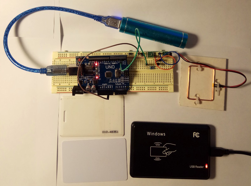
Assembled emulator
Let's have a closer look. I intentionally used a separate little PCB for the capacitor, where it was soldered right on the pins, inserted into the breadboard.

My original intention was to check the operability of the emulator using another RDM6300 (I bought two of these). And I even did that at first, but then decided that it's kind of wrong to debug one Arduino using another and purchased an off-the-shelf reader.

Off-the-shelf reader
Programming the timer
Here are a few nuances, which are essential to get an understanding of what I’m doing.
Remind, that EM4102 uses a Manchester coding scheme, and when the EM4102 protocol is modulated a bit can be transmitted at a rate of 64/32/16 carrier cycles (125kHz).

Simply put, when a bit is transmitted, either the value of
1 changes to 0 (when transmitting0) or the value of 0 changes to 1 (when transmitting 1). Therefore, if we transmit a bit of information at a rate of 64 carrier cycles, then we use 32 carrier cycles to transmit a «half-bit». So, every «half-bit» should change with a frequency of:f=125000/32 = 3906,25 HzA period of this «half-bit» will last for 256 μs.
Now we need to calculate the parameters of the timer, so that it changes the output state with that frequency. But I became so lazy, that after opening a datasheet began to yawn and finally decided to find a ready solution. As it turned out, some timer calculations were readily available and the only thing left was to provide initial data. Meet a calculator for Arduino timer.
All you need is to type in the timer frequency, which is 3906Hz, and the program will generate a ready-to-use code. Cool, isn’t it?

Note, that I entered the frequency as integers, while the program calculated its fractional representation, which is exactly what we need. As a result, I got the following timer initialization code:
void setupTimer1() {
  noInterrupts();
  // Clear registers
  TCCR1A = 0;
  TCCR1B = 0;
  TCNT1 = 0;

  // 3906.25 Hz (16000000/((4095+1)*1))
  OCR1A = 4095;
  // Prescaler 1
  TCCR1B |= (1 << CS10);
  // Output Compare Match A Interrupt Enable
  TIMSK1 |= (1 << OCIE1A);
  interrupts();
}
Brilliant, simple, and concise!
The output interruption vector also has a simple structure. Remind, that we need to change from
1 to 0 when transmitting0 and from 0 to 1 when transmitting 1 (see the diagram above). So, we check what is being transmitted and in which part of the «half-bit» we are now, gradually reading all the data from the data array. ISR(TIMER1_COMPA_vect) {
TCNT1=0;
if (((data[byte_counter] << bit_counter)&0x80)==0x00) {
if (half==0) digitalWrite(ANTENNA, LOW);
if (half==1) digitalWrite(ANTENNA, HIGH);
}
else {
if (half==0) digitalWrite(ANTENNA, HIGH);
if (half==1) digitalWrite(ANTENNA, LOW);
}
half++;
if (half==2) {
half=0;
bit_counter++;
if (bit_counter==8) {
bit_counter=0;
byte_counter=(byte_counter+1)%8;
}
}
}
Converting data for transmitting
Here, we also need to refresh how the data is stored on the card. Let’s see an actual example.
Suppose, we have a card but don’t have a reader. There is a number printed on the card: 010,48351.

A real card with the number 010, 48351
How can we translate this number to the ID stored on the card? That’s simple. Recall the formula, which supposes translating two parts of the number separately:
010d = 0xA
48351d = 0xBCDF
As a result, we get our serial number as
0xABCDF. Let’s check it by scanning the card with the reader. We get a decimal number: 0000703711Then, we convert it to a hex-string and here is that number again:
0xABCDF.It seems quite simple, but there is a complex part ahead. I’ll remind you of the format in which the data is stored on the card.

Detailed explanation:
- First, there are nine ones in the header.
- The lower nibble of the client’s ID
- A parity bit in the end.
- The second nibble of the client’s ID.
- A parity bit.
- The lower nibble of the zero byte of the serial number.
- A parity bit.
- The upper nibble of the zero byte of the serial number.
- The rest of the data is transmitted the same way through nibbles with a parity bit in the end.
- The most difficult part. The parity bits are calculated for all 10 nibbles.
- Finally, all this beastliness ends with a stop bit, which is always
0.
As a result, we get 64 bits of data (from 5 bytes!). Here, I should mention that my reader doesn’t read the client’s ID, so I take it as 0.
What is a parity bit? A parity bit is used to check for errors during transmitting. To know its value we calculate the number of ones in the transmitted data. if it's even, then the bit is
0, and if it’s not, then the bit is 1. XOR is the easiest way to calculate it. I spent much time thinking of how to elegantly convert the serial number to the transmitted data so that it also would take less memory of the MCU. Finally, I sketched a small program that does just that. The program can be found under the spoiler below.
Program for testing conversion of a serial number into transmitted data
#include <stdio.h>
#include <stdlib.h>
#include <stdint.h>

#define BYTE_TO_BINARY_PATTERN "%c%c%c%c%c%c%c%c"
#define BYTE_TO_BINARY(byte)  \
  (byte & 0x80 ? '1' : '0'), \
  (byte & 0x40 ? '1' : '0'), \
  (byte & 0x20 ? '1' : '0'), \
  (byte & 0x10 ? '1' : '0'), \
  (byte & 0x08 ? '1' : '0'), \
  (byte & 0x04 ? '1' : '0'), \
  (byte & 0x02 ? '1' : '0'), \
  (byte & 0x01 ? '1' : '0')

#define NYBBLE_TO_BINARY_PATTERN "%c%c%c%c"
#define NYBBLE_TO_BINARY(byte)  \
	(byte & 0x08 ? '1' : '0'), \
	(byte & 0x04 ? '1' : '0'), \
	(byte & 0x02 ? '1' : '0'), \
	(byte & 0x01 ? '1' : '0')


int main() {
	//unsigned long long card_id = 0x00000ABCDF;
	//uint64_t card_id = 0x00000ABCDF;
	uint64_t card_id = (uint64_t)3604000;
	uint64_t data_card_ul = 0x1FFF; //first 9 bit as 1
	int32_t i;
	uint8_t tmp_nybble;
	uint8_t column_parity_bits = 0;
	printf("card_id = 0x%lX\n", card_id);
	for (i = 9; i >= 0; i--) { //5 bytes = 10 nybbles
		tmp_nybble = (uint8_t) (0x0f & (card_id >> i*4));
		data_card_ul = (data_card_ul << 4) | tmp_nybble;
		printf("0x%02X", (int) tmp_nybble);
		printf("\t"NYBBLE_TO_BINARY_PATTERN, NYBBLE_TO_BINARY(tmp_nybble));
		printf("\t %d\n", (tmp_nybble >> 3 & 0x01) ^ (tmp_nybble >> 2 & 0x01) ^\
			(tmp_nybble >> 1 & 0x01) ^ (tmp_nybble  & 0x01));
		data_card_ul = (data_card_ul << 1) | ((tmp_nybble >> 3 & 0x01) ^ (tmp_nybble >> 2 & 0x01) ^\
			(tmp_nybble >> 1 & 0x01) ^ (tmp_nybble  & 0x01));
		column_parity_bits ^= tmp_nybble;
	}
	data_card_ul = (data_card_ul << 4) | column_parity_bits;
	data_card_ul = (data_card_ul << 1); //1 stop bit = 0
	printf("\t"NYBBLE_TO_BINARY_PATTERN"\n", NYBBLE_TO_BINARY(column_parity_bits));
	printf("data_card_ul = 0x%lX\n", data_card_ul);

	for (i = 7; i >= 0; i--) {
		printf("0x%02X,", (int) (0xFF & (data_card_ul >> i * 8)));
	}
	printf("\n");
	return 0;
}
Most of all, we are interested in the parity bits. For convenience, I made the output on the screen look the same as in the table. Here is the result.

card_id — is the card’s serial number (which was mentioned above).The first column holds nibbles, the second one shows their bit representation and the third column represents the parity bit. The third row from the bottom contains the parity bits of all the nibbles. As I already said, they're calculated with XOR.
After testing all the calculations and matching them visually I checked the resulting data in an Arduino program (the last row from the picture should be inserted in code). All had worked just fine. Thanks to the sketched program, now I can easily convert any serial number to the transmitted data. Earlier, the bit calculations were carried out by individual programs on my PC and I didn't like such a cumbersome process. That said, the function for translating a serial number into the transmitted format looks as follows:
#define CARD_ID 0xABCDF

uint8_t data[8];

void data_card_ul() {
  uint64_t card_id = (uint64_t)CARD_ID;
  uint64_t data_card_ul = (uint64_t)0x1FFF; //first 9 bit as 1
  int32_t i;
  uint8_t tmp_nybble;
  uint8_t column_parity_bits = 0;
  for (i = 9; i >= 0; i--) { //5 bytes = 10 nibbles
    tmp_nybble = (uint8_t) (0x0f & (card_id >> i*4));
    data_card_ul = (data_card_ul << 4) | tmp_nybble;
    data_card_ul = (data_card_ul << 1) | ((tmp_nybble >> 3 & 0x01) ^ (tmp_nybble >> 2 & 0x01) ^\
      (tmp_nybble >> 1 & 0x01) ^ (tmp_nybble  & 0x01));
    column_parity_bits ^= tmp_nybble;
  }
  data_card_ul = (data_card_ul << 4) | column_parity_bits;
  data_card_ul = (data_card_ul << 1); //1 stop bit = 0
  for (i = 0; i < 8; i++) {
    data[i] = (uint8_t)(0xFF & (data_card_ul >> (7 - i) * 8));
  }
}
That’s it! Time for testing a real scenario. The project’s source code can be found here.
Test run
It is better to see something once than to read about it a thousand times as they speak. I also decided to record a demonstration of the working emulator. I had an idea to test it with real hardware and tried to sneak inside our company’s office building with the help of Arduino, but due to the damn pandemic restrictions, no one is allowed in. That’s why I had to run a full-scale test on my lab table.
Conclusion
I do hope that such kinds of articles will encourage neophytes to master programming and electronics. Besides, it would be good if this information facilitated the removal of such unprotected and unsafe cards from the market, as now they can be easily cloned and emulated by even a kid.
Resources

