Introduction
As first-year students of Innopolis University, we had an opportunity to make our own project in computer architecture. University suggested us several projects and we have chosen to make a stack-based calculator with reverse polish notation. One of the requirements for the project is to use FPGA board provided by the university.

As our board, we have chosen Cyclon IV. Therefore, we had to write code on hardware description language. In the course we have studied Verilog, so we have chosen it. Also, the university has additional modules for FPGA, such as numpad, thus we decided to use it in our project.
In this article, we want to share our knowledge about FPGA and Verilog, also provide you with a tutorial to repeat our project.
Basic design
We formed a group of two people and organized our first meeting. There we have discussed basic design, divided our responsibilities and have made a short plan with deadlines. This is what we come up with. We need to:
- Implement stack in the Verilog
- Learn how to work with the numpad
- Implement output through the 8-segment display located on the FPGA board
- Make a main module that will connect all modules together

Each member of the team has chosen themselves a module to write. The first-order task was to implement stack, output, and input. As it was determined, we have begun to work.
Stack
In the stack, we store all our operands. To store them, we devoted 32 words of memory.
Stack module code
module stack(
	//Just 50 MHz clock
	input clock,

	//Reset signal
	input reset,

	//PUSH operation control signal
	input push,

	//POP operation control signal
	input pop,

	//SWAP operation control signal
	input swap,

	//UPDATE operation control signal
	input write,

	//Value to write
	input [31:0] value,

	//Top element
	output [31:0] top,

	//Second element from stack top
	output [31:0] next,

	//Total elements count
	output [5:0] count,

	//Stack overflow error
	output error
);

//Stack memory for 32 words
reg [31:0] memory [0:31];

//Stack pointer on top element, indexing from 0
reg [5:0] pointer = 0;

//First element by default is 0
initial memory[0] = 0;

//Top stack element
assign top = memory[pointer];

//Second element if such exists, 0 otherwise
assign next = pointer == 0 ? 0 : memory[pointer - 1];

//Stack elements count
assign count = pointer[4:0] + 1;

//Stack overflow signal
assign error = pointer[5];

always @(posedge clock)
begin
	//Reseting
	if (reset)
	begin
		memory[0] <= 0;
		pointer <= 0;
	end

	//Remove one element form stack
	if (pop)
		pointer <= pointer - 1;

	//Swaps top and next elements
	if (swap)
	begin
		memory[pointer] <= memory[pointer - 1];
		memory[pointer - 1] <= memory[pointer];
	end

	//Update top element
	if (write)
		memory[pointer - pop] <= value;

	//Push new zero element on top
	if (push)
	begin
		pointer <= pointer + 1;

		//Here pointer is still not updated, so +1
		memory[pointer + 1] <= 0;
	end
end

endmodule
It is just a regular stack. If a new value is pushed to it is just increases the pointer and puts this value to the top of the stack. If a value is popped out of stack it decreases the pointer and updates the top element.

For a convenience, we added a reset button, in order to have an opportunity to restart our programme while execution. Also, for debugging was added an opportunity to catch stack overflow error.
Display
In this module, we implemented all the functionality of the display. It is able to dynamically show results of our computations and also an input values.
Here is the code for the display
module display_bcd (
	//Just 50 MHz clock
	input clock,

	//Switching hexademical and decimal representations
	input show_in_hex,

	//Asserted if something is going wrong, displaing error message
	input error,

	//Value to be displayed in binary format
	input [31:0] value,

	//Segments of display
	output [7:0] control,

	//LEDs of one segment
	output [7:0] leds
);

//  ###0###
// #       #
// #       #
// 5       1
// #       #
// #       #
//  ###6###
// #       #
// #       #
// 4       2
// #       # ###
// #       # #7#
//  ###3###  ###

//All representation of used symbols
parameter D_0 = 8'b00111111;
parameter D_1 = 8'b00000110;
parameter D_2 = 8'b01011011;
parameter D_3 = 8'b01001111;
parameter D_4 = 8'b01100110;
parameter D_5 = 8'b01101101;
parameter D_6 = 8'b01111101;
parameter D_7 = 8'b00000111;
parameter D_8 = 8'b01111111;
parameter D_9 = 8'b01101111;
parameter D_DOT = 8'b10000000;
parameter D_A = 8'b01110111;
parameter D_B = 8'b01111100;
parameter D_C = 8'b01011000;
parameter D_D = 8'b01011110;
parameter D_E = 8'b01111001;
parameter D_F = 8'b01110001;
parameter D_R = 8'b01010000;
parameter D_O = 8'b01011100;
parameter D_MINUS = 8'b01000000;
parameter D_EMPTY = 8'b00000000;

parameter D_E_CODE = 14;
parameter D_R_CODE = 16;
parameter D_O_CODE = 17;
parameter D_MINUS_CODE = 18;
parameter D_EMPTY_CODE = 31;

//Delay counter, delaying 8192 clock cycles ~ 0.16 ms
reg [12:0] counter = 0;

//Saved Binary-Coded Decimal
reg [31:0] r_bcd;

//Number of segment that is active on current iteration
reg [2:0] ctrl = 0;

//Current digit shown on the current segment
reg [4:0] digit;

//Asserted for 1 cycle when conversion to Binary-Coded Decimal is done
wire converted;

//Intermediate Binary-Coded decimal value
wire [31:0] bcd;

//Decoded number digits
wire [31:0] digits;

//Number sign
wire sign;

//Digits from unsigned numbers
wire [31:0] unsigned_number;

bcd_convert #(32, 8) bcd_convert(
	.i_Clock(clock),
	.i_Binary(unsigned_number),
	.i_Start(1'b1),
	.o_BCD(bcd),
	.o_DV(converted));

//Get number sign
assign sign = value[31];

//Get unsigned number
assign unsigned_number = sign ? -value : value;

//Switching final number representation
assign digits = show_in_hex ? unsigned_number : r_bcd;

//Constolling segments
assign control = ~(1 << ctrl);


reg [7:0] r_leds;

//Controlling LEDs
assign leds = ~r_leds;


always @(posedge clock)
begin
	case (digit)
		0: r_leds <= D_0;
		1: r_leds <= D_1;
		2: r_leds <= D_2;
		3: r_leds <= D_3;
		4: r_leds <= D_4;
		5: r_leds <= D_5;
		6: r_leds <= D_6;
		7: r_leds <= D_7;
		8: r_leds <= D_8;
		9: r_leds <= D_9;
		10: r_leds <= D_A;
		11: r_leds <= D_B;
		12: r_leds <= D_C;
		13: r_leds <= D_D;
		14: r_leds <= D_E;
		15: r_leds <= D_F;
		16: r_leds <= D_R;
		17: r_leds <= D_O;
		18: r_leds <= D_MINUS;
		default: r_leds <= D_EMPTY;
	endcase

	if (error)
		//Display error message
		case(ctrl)
			0: digit <= D_R_CODE;
			1: digit <= D_O_CODE;
			2: digit <= D_R_CODE;
			3: digit <= D_R_CODE;
			4: digit <= D_E_CODE;
			5: digit <= D_EMPTY_CODE;
			6: digit <= D_EMPTY_CODE;
			7: digit <= D_EMPTY_CODE;
		endcase
	else
		//Select current digit
		case(ctrl)
			0: digit <= digits[3:0];
			1: digit <= digits[31:4] ? digits[7:4] : D_EMPTY_CODE;
			2: digit <= digits[31:8] ? digits[11:8] : D_EMPTY_CODE;
			3: digit <= digits[31:12] ? digits[15:12] : D_EMPTY_CODE;
			4: digit <= digits[31:16] ? digits[19:16] : D_EMPTY_CODE;
			5: digit <= digits[31:20] ? digits[23:20] : D_EMPTY_CODE;
			6: digit <= digits[31:24] ? digits[27:24] : D_EMPTY_CODE;
			7: digit <= sign ? D_MINUS_CODE : (digits[31:28] ? digits[31:28] : D_EMPTY_CODE);
		endcase

	//Increase current delay
	counter <= counter + 1;

	//Delay is done, increase segment number
	if (counter == 13'b1000000000000)
		ctrl <= ctrl + 1;

	//Save converted Binary-Coded Decimal
	if (converted)
		r_bcd <= bcd;
end

endmodule
Cyclone IV has eight eight-segment displays. They are controlled by 16 pins. Eight pins control segments in each display (let's call it led) and another eight pins control which of the display will be active (just call it control). For example, if we need to show digit 5 on the third display, control should be 00000100 and led should be 01101101 (according to the scheme in the code). To display several different digits on different displays, we need to light up periodically each display. So, each 8192 clock cycles, we move left logically by 1 bit our control output, which is initially equal to 00000001. When we move it, we change the number to be displayed currently. It happens so fast, that our eye cannot see the changes, thus, we can show different digits in each display.

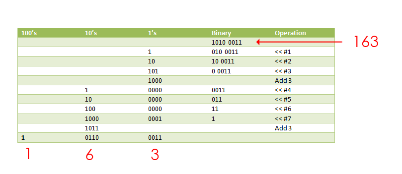
As we pass to this module binary number, we need to somehow represent it as separate digits. For this purpose we found a module that makes it, using double dabble algorithm. It takes as an input our binary number and returns it as a binary coded decimal (4 bit per digit).
Here is the code for it
module bcd_convert
  #(parameter INPUT_WIDTH,
	parameter DECIMAL_DIGITS)
  (
   input                         i_Clock,
   input [INPUT_WIDTH-1:0]       i_Binary,
   input                         i_Start,
   //
   output [DECIMAL_DIGITS*4-1:0] o_BCD,
   output                        o_DV
   );

  parameter s_IDLE              = 3'b000;
  parameter s_SHIFT             = 3'b001;
  parameter s_CHECK_SHIFT_INDEX = 3'b010;
  parameter s_ADD               = 3'b011;
  parameter s_CHECK_DIGIT_INDEX = 3'b100;
  parameter s_BCD_DONE          = 3'b101;

  reg [2:0] r_SM_Main = s_IDLE;

  // The vector that contains the output BCD
  reg [DECIMAL_DIGITS*4-1:0] r_BCD = 0;

  // The vector that contains the input binary value being shifted.
  reg [INPUT_WIDTH-1:0]      r_Binary = 0;

  // Keeps track of which Decimal Digit we are indexing
  reg [DECIMAL_DIGITS-1:0]   r_Digit_Index = 0;

  // Keeps track of which loop iteration we are on.
  // Number of loops performed = INPUT_WIDTH
  reg [7:0]                  r_Loop_Count = 0;

  wire [3:0]                 w_BCD_Digit;
  reg                        r_DV = 1'b0;

  always @(posedge i_Clock)
	begin

	  case (r_SM_Main)

		// Stay in this state until i_Start comes along
		s_IDLE :
		  begin
			r_DV <= 1'b0;

			if (i_Start == 1'b1)
			  begin
				r_Binary  <= i_Binary;
				r_SM_Main <= s_SHIFT;
				r_BCD     <= 0;
			  end
			else
			  r_SM_Main <= s_IDLE;
		  end


		// Always shift the BCD Vector until we have shifted all bits through
		// Shift the most significant bit of r_Binary into r_BCD lowest bit.
		s_SHIFT :
		  begin
			r_BCD     <= r_BCD << 1;
			r_BCD[0]  <= r_Binary[INPUT_WIDTH-1];
			r_Binary  <= r_Binary << 1;
			r_SM_Main <= s_CHECK_SHIFT_INDEX;
		  end


		// Check if we are done with shifting in r_Binary vector
		s_CHECK_SHIFT_INDEX :
		  begin
			if (r_Loop_Count == INPUT_WIDTH-1)
			  begin
				r_Loop_Count <= 0;
				r_SM_Main    <= s_BCD_DONE;
			  end
			else
			  begin
				r_Loop_Count <= r_Loop_Count + 1;
				r_SM_Main    <= s_ADD;
			  end
		  end


		// Break down each BCD Digit individually.  Check them one-by-one to
		// see if they are greater than 4.  If they are, increment by 3.
		// Put the result back into r_BCD Vector.
		s_ADD :
		  begin
			if (w_BCD_Digit > 4)
			  begin
				r_BCD[(r_Digit_Index*4)+:4] <= w_BCD_Digit + 3;
			  end

			r_SM_Main <= s_CHECK_DIGIT_INDEX;
		  end


		// Check if we are done incrementing all of the BCD Digits
		s_CHECK_DIGIT_INDEX :
		  begin
			if (r_Digit_Index == DECIMAL_DIGITS-1)
			  begin
				r_Digit_Index <= 0;
				r_SM_Main     <= s_SHIFT;
			  end
			else
			  begin
				r_Digit_Index <= r_Digit_Index + 1;
				r_SM_Main     <= s_ADD;
			  end
		  end


		s_BCD_DONE :
		  begin
			r_DV      <= 1'b1;
			r_SM_Main <= s_IDLE;
		  end


		default :
		  r_SM_Main <= s_IDLE;

	  endcase
	end // always @ (posedge i_Clock)


  assign w_BCD_Digit = r_BCD[r_Digit_Index*4 +: 4];

  assign o_BCD = r_BCD;
  assign o_DV  = r_DV;

endmodule // Binary_to_BCD
This module works with a very interesting algorithm. It shifts all the bits in the number to the left one-by-one and, if the first 4 bits are bigger than 4 in decimal, it adds decimal 3 to them.
Numpad
This module works with the numpad. It reads the value from the numbpad and passes it to the main module. We have two states of the keyboard. They can be switched by pressing one of the buttons on the fpga.
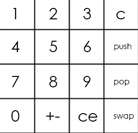
The main keyboard looks like that:
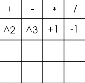
And the alternate like that:
The numpad code
module numpad (
	//Just 50 MHz clock
	input clock,

	//Alternative keyboard
	input alt_key,

	//Alternative keyboard indicator
	output alt_led,

	//Numpad rows
	input [3:0] rows,

	//Numpad columns
	output [3:0] columns,

	//State change description [5:5] - is_changed, [4:4] - keyboard, [3:0] - button
	output [5:0] value
);

//  col 0  col 1  col 2  col 3
//
// #############################
// #      #      #      #      #
// # 1(0) # 2(4) # 3(8) # A(12)#  row 0
// #      #      #      #      #
// #############################
// #      #      #      #      #
// # 4(1) # 5(5) # 6(9) # B(13)#  row 1
// #      #      #      #      #
// #############################
// #      #      #      #      #
// # 7(2) # 8(6) # 9(10)# C(14)#  row 2
// #      #      #      #      #
// #############################
// #      #      #      #      #
// # 0(3) # F(7) # E(11)# D(15)#  row 3
// #      #      #      #      #
// #############################

parameter BTN_EMPTY = 6'b000000;

//Previous pressed button
reg [5:0] prev = 0;

//Current pressed button
reg [5:0] cur = 0;

//Current column number
reg [1:0] col = 0;

//Counter for delay
reg [8:0] counter = 0;

//Rows pressed flags
reg [3:0] pressed = 0;

//Is alternative keyboard
reg is_alt = 0;

//Alt key on prev clock cycle
reg prev_alt_key = 0;

//Controlling column
assign columns = ~(1 << col);

assign alt_led = ~is_alt;

always @(posedge clock)
begin
	//Increase counter
	counter <= counter + 1;

	//Evaluating alternative keyboard signal
	if (value != BTN_EMPTY)
		is_alt <= 0;
	else
		is_alt <= (alt_key == 1 && prev_alt_key == 0) ? ~is_alt : is_alt;
	prev_alt_key <= alt_key;

	if (counter == 9'b1111111111)
	begin
		//Evaluating current button
		case(~rows)
			4'b0001:
			begin
			pressed[col] <= 1;
			cur <= {1'b1, ~is_alt, col, 2'b00};
			end
			4'b0010:
			begin
			pressed[col] <= 1;
			cur <= {1'b1, ~is_alt, col, 2'b01};
			end
			4'b0100:
			begin
			pressed[col] <= 1;
			cur <= {1'b1, ~is_alt, col, 2'b10};
			end
			4'b1000:
			begin
			pressed[col] <= 1;
			cur <= {1'b1, ~is_alt, col, 2'b11};
			end
			default:
			begin
			pressed[col] <= 0;
			cur <= pressed ? cur : BTN_EMPTY;
			end
		endcase
	end

	//increase column number when counter is 9'011111111, using different edges of counter[8] to let counter pass through zero, to assert wire value if need
	if (counter == 9'b011111111)
	begin
		//Saving previous button every 4 iterations
		if (&col)
			prev <= cur;

		col <= col + 1;
	end
end

//Evaluating state change
//Comparing current and previous states without keyboard bit
assign value = (counter == 9'b000000000 && col == 2'b11 && {prev[5], prev[3:0]} != {cur[5], cur[3:0]}) ? cur : BTN_EMPTY;

endmodule
So, the numpad is a scheme that contains 16 buttons (4 rows and 4 columns). To get the number of the button that was pressed we need 4 outputs (let it be columns) and 4 inputs (rows). We pass the voltage to each column periodically and if the button is pressed, circuit is closed and certain row gets true as an input. Combination of the number of the column and the number of the row uniquely determine our button.

If we use main keyboard on the example above, we will get number 5 as an input.
Main module
The main module connects all the parts together and actually makes calculations.
The main module here
module main(
	//Just 50 MHz clock
	input clock,

	//Reset signal
	input reset,

	//Representation switch
	input show_in_hex,

	//Show stack elements count switch
	input show_count,

	//Button, switches to operations keyboard
	input alt_numpad_key,

	//Alternative keyboard indicator
	output alt_numpad_led,

	//Numpad rows and columns
	input [3:0] numpad_rows,
	output [3:0] numpad_columns,

	//Display and display control
	output [7:0] display_leds,
	output [7:0] display_control
);

// 1  2  3  C
// 4  5  6  PUSH
// 7  8  9  POP
// 0  +- CE SWAP

parameter BTN_0 = 6'b110011;
parameter BTN_1 = 6'b110000;
parameter BTN_2 = 6'b110100;
parameter BTN_3 = 6'b111000;
parameter BTN_4 = 6'b110001;
parameter BTN_5 = 6'b110101;
parameter BTN_6 = 6'b111001;
parameter BTN_7 = 6'b110010;
parameter BTN_8 = 6'b110110;
parameter BTN_9 = 6'b111010;
parameter BTN_CLEAR_DIGIT = 6'b111100;
parameter BTN_PUSH = 6'b111101;
parameter BTN_POP = 6'b111110;
parameter BTN_SWAP = 6'b111111;
parameter BTN_CLEAR_NUMBER = 6'b111011;
parameter BTN_UNARY_MINUS = 6'b110111;

//  +   -   *   /
// sqr cbe inc dec

parameter BTN_ADDITION = 6'b100000;
parameter BTN_SUBTRACTION = 6'b100100;
parameter BTN_MULTIPLICATION = 6'b101000;
parameter BTN_DIVISION = 6'b101100;
parameter BTN_SQUARE = 6'b100001;
parameter BTN_CUBE = 6'b100101;
parameter BTN_INCREMENT = 6'b101001;
parameter BTN_DECREMENT = 6'b101101;

//Numpad state
wire [5:0] pressed;

//Stack elements count
wire [5:0] count;

//First and second stack elements
wire [31:0] top, next;

wire stack_error;

//Evaluated new value
reg [31:0] new_value;

//Stack control signals
reg write, push, pop, swap;

reg arithmetic_error = 0;

numpad numpad(
	.clock (clock),
	.alt_key (~alt_numpad_key),
	.alt_led (alt_numpad_led),
	.rows (numpad_rows),
	.columns (numpad_columns),
	.value (pressed)
);

stack stack(
	.clock (clock),
	.reset (~reset),
	.push (push),
	.pop (pop),
	.swap (swap),
	.write (write),
	.value (new_value),
	.top (top),
	.next (next),
	.count (count),
	.error (stack_error)
);

display_bcd display(
	.clock (clock),
	.error (stack_error || arithmetic_error),
	.show_in_hex (show_in_hex),
	.value (show_count ? count : top),
	.control (display_control),
	.leds (display_leds)
);

// Division result
wire [31:0] res;
assign res = ((next[31] ? -next : next) / (top[31] ? -top : top));

always @(posedge clock)
begin
	//Reseting arithmetic error
	if (~reset)
		arithmetic_error <= 0;

	case (pressed)
		BTN_0:
		begin
			write <= 1;
			new_value <= top * 10;
		end
		BTN_1:
		begin
			write <= 1;
			new_value <= top * 10 + (top[31] ? -1 : 1);
		end
		BTN_2:
		begin
			write <= 1;
			new_value <= top * 10 + (top[31] ? -2 : 2);
		end
		BTN_3:
		begin
			write <= 1;
			new_value <= top * 10 + (top[31] ? -3 : 3);
		end
		BTN_4:
		begin
			write <= 1;
			new_value <= top * 10 + (top[31] ? -4 : 4);
		end
		BTN_5:
		begin
			write <= 1;
			new_value <= top * 10 + (top[31] ? -5 : 5);
		end
		BTN_6:
		begin
			write <= 1;
			new_value <= top * 10 + (top[31] ? -6 : 6);
		end
		BTN_7:
		begin
			write <= 1;
			new_value <= top * 10 + (top[31] ? -7 : 7);
		end
		BTN_8:
		begin
			write <= 1;
			new_value <= top * 10 + (top[31] ? -8 : 8);
		end
		BTN_9:
		begin
			write <= 1;
			new_value <= top * 10 + (top[31] ? -9 : 9);
		end
		BTN_CLEAR_DIGIT:
		begin
			write <= 1;
			new_value <= top / 10;
		end
		BTN_CLEAR_NUMBER:
		begin
			write <= 1;
			new_value <= 0;
		end
		BTN_PUSH:
		begin
			push <= 1;
		end
		BTN_POP:
		begin
			pop <= 1;
		end
		BTN_SWAP:
		begin
			swap <= 1;
		end
		BTN_UNARY_MINUS:
		begin
			write <= 1;
			new_value <= -top;
		end
		BTN_ADDITION:
		begin
			pop <= 1;
			write <= 1;
			new_value <= next + top;
		end
		BTN_SUBTRACTION:
		begin
			pop <= 1;
			write <= 1;
			new_value <= next - top;
		end
		BTN_MULTIPLICATION:
		begin
			pop <= 1;
			write <= 1;
			new_value <= next * top;
		end
		BTN_DIVISION:
		begin
			pop <= 1;
			write <= 1;
			new_value <= (next[31] ^ top[31] ? -res : res);
			arithmetic_error <= ~(|top);
		end
		BTN_SQUARE:
		begin
			write <= 1;
			new_value <= top * top;
		end
		BTN_CUBE:
		begin
			write <= 1;
			new_value <= top * top * top;
		end
		BTN_INCREMENT:
		begin
			write <= 1;
			new_value <= top + 1;
		end
		BTN_DECREMENT:
		begin
			write <= 1;
			new_value <= top - 1;
		end
		default: // Nothing usefull is pressed
		begin
			write <= 0;
			push <= 0;
			pop <= 0;
			swap <= 0;
		end
	endcase
end

endmodule
The «always» block contains case statement which is choosing operation depending on which button of the numpad is pressed. If a button with the digit pressed, then this digit goes to the top of the stack. If we need to enter the number that has more than one digit, then the top number in the stack is multiplied by 10 and this multiplied value goes to the top of the stack. If the button with an operation is pressed, this operation is applying to first two numbers in the stack.

During the testing, we found an interesting thing about division in Verilog. For some strange reason if we will try to divide two negative numbers the operation will yield a zero as a result. So, in order to fix it, we had to add a branch to process this case explicitly.
Conclusion
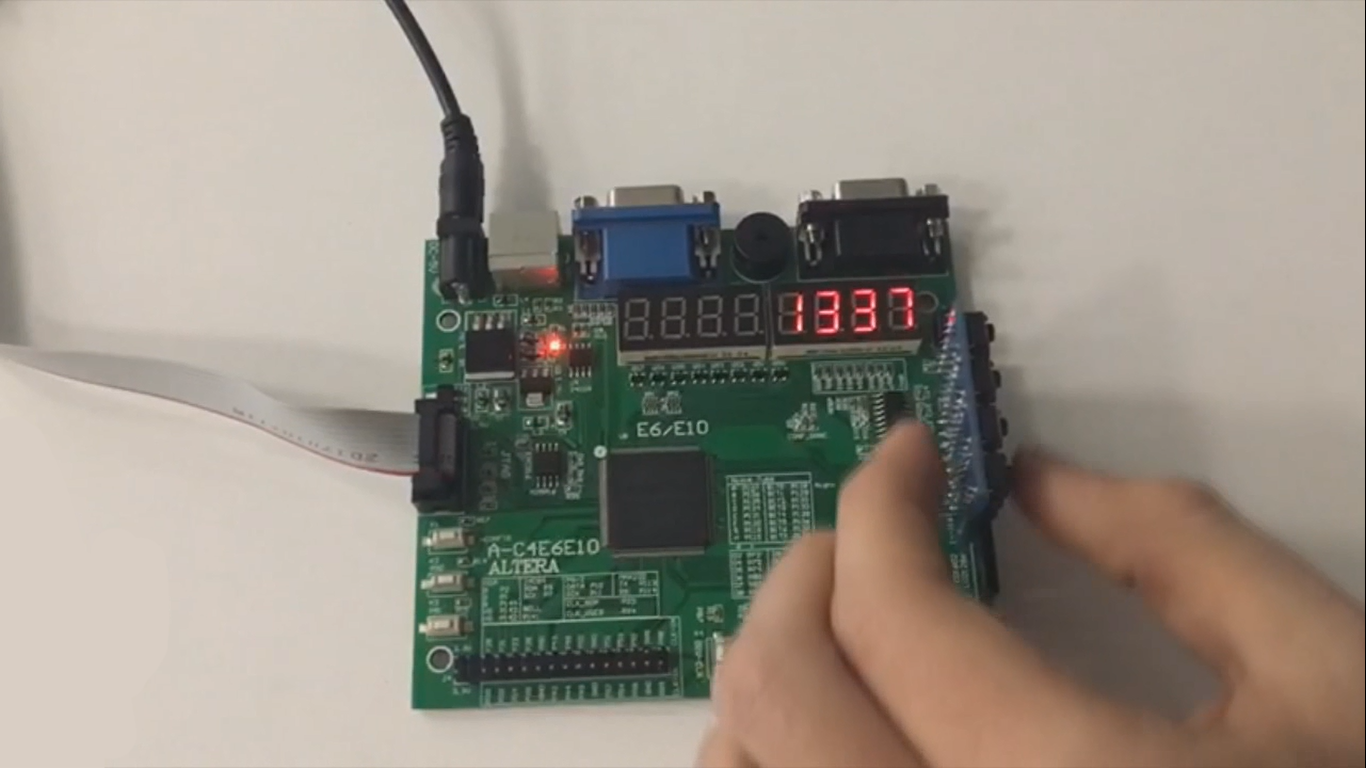
Here is the video, that demonstrates the work of the calculator. Also, here is the github of our project.
Studying Verilog drastically increased our understanding of the architecture of the computer. Besides, working in a team has helped us develop basic soft skills for teamwork.
Authors: Fedoseev Kirill, Yuloskov Artem.

