Привет хабровчане! Не так давно попалась мне в руки пара плат Arduino Nano со встроенным модулем NRF24L01, которые оказались достойной заменой популярной связки Arduino Nano + NRF24L01. Модуль NRF24L01 часто используется в различных проектах для обеспечения надежной беспроводной передачи данных. Небольшая цена, низкая задержка и энергопотребление, а также возможность выбора до128 каналов связи дает NRF24L01 преимущество перед другими радиочастотными модулями, такими как wifi, bluetooth, Zigbee и т.д.
В данной статье хочу поделиться с вами своим первым опытом работы как с Arduino RF, так и с NRF24L01 в целом.

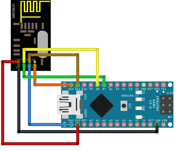
Изображенную выше плату можно приобрести на Aliexpress. Данная плата является аналогом следующей схемы:
Для тестирования схемы я использую библиотеку RF24. В рамках данного обзора я рассмотрю:
передачу данных между платами Arduino RF;
передачу данных между Arduino RF и Raspberry Pi;
сравнение со связкой Arduino + модуль NRF24L01.
Передача данных между платами Arduino RF
Обе платы Arduino RF подключаются к портам одного ноутбука. Для работы с платами я использую среду Arduino Studio, в которой выполняю следующие настройки:
Tools -> Boards-> Arduino AVR Boards->Arduino Nano
Tools -> Processor-> ATmega328P (Old Bootloader)
Tools -> Managie Libraries-> "RF24" -> установка последней версии библиотеки RF24 by TMRh20 ( у меня версия 1.4.1). Также понадобятся библиотеки SPI.h и printf.h
работа с разными портами в Arduino Studio
Если у вас есть проблема одновременного открытия двух окон SerialMonitor, в которые выводится информация от двух Arduino, подключенных к разным портам, нужно сначала запустить ArduinoStuio в обычном режиме и отобразить информацию с одного порта, а потом запустить среду ArduinoStuio в режиме "от администратора" и отобразить информацию с другого порта.
Для проверки плат использовался пример, поставляемый с библиотекой RF24, который нужно загрузить на обе платы Arduino.
Files-> Examples-> GettingStarted
код программы GettingStarted.ino
/*
 * See documentation at https://nRF24.github.io/RF24
 * See License information at root directory of this library
 * Author: Brendan Doherty (2bndy5)
 */

/**
 * A simple example of sending data from 1 nRF24L01 transceiver to another.
 *
 * This example was written to be used on 2 devices acting as "nodes".
 * Use the Serial Monitor to change each node's behavior.
 */
#include <SPI.h>
#include "printf.h"
#include "RF24.h"

// instantiate an object for the nRF24L01 transceiver
RF24 radio(7, 8); // using pin 7 for the CE pin, and pin 8 for the CSN pin

// Let these addresses be used for the pair
uint8_t address[][6] = {"1Node", "2Node"};
// It is very helpful to think of an address as a path instead of as
// an identifying device destination

// to use different addresses on a pair of radios, we need a variable to
// uniquely identify which address this radio will use to transmit
bool radioNumber = 1; // 0 uses address[0] to transmit, 1 uses address[1] to transmit

// Used to control whether this node is sending or receiving
bool role = false;  // true = TX role, false = RX role

// For this example, we'll be using a payload containing
// a single float number that will be incremented
// on every successful transmission
float payload = 0.0;

void setup() {

  Serial.begin(115200);
  while (!Serial) {
    // some boards need to wait to ensure access to serial over USB
  }

  // initialize the transceiver on the SPI bus
  if (!radio.begin()) {
    Serial.println(F("radio hardware is not responding!!"));
    while (1) {} // hold in infinite loop
  }

  // print example's introductory prompt
  Serial.println(F("RF24/examples/GettingStarted"));

  // To set the radioNumber via the Serial monitor on startup
  Serial.println(F("Which radio is this? Enter '0' or '1'. Defaults to '0'"));
  while (!Serial.available()) {
    // wait for user input
  }
  char input = Serial.parseInt();
  radioNumber = input == 1;
  Serial.print(F("radioNumber = "));
  Serial.println((int)radioNumber);

  // role variable is hardcoded to RX behavior, inform the user of this
  Serial.println(F("*** PRESS 'T' to begin transmitting to the other node"));

  // Set the PA Level low to try preventing power supply related problems
  // because these examples are likely run with nodes in close proximity to
  // each other.
  radio.setPALevel(RF24_PA_LOW);  // RF24_PA_MAX is default.

  // save on transmission time by setting the radio to only transmit the
  // number of bytes we need to transmit a float
  radio.setPayloadSize(sizeof(payload)); // float datatype occupies 4 bytes

  // set the TX address of the RX node into the TX pipe
  radio.openWritingPipe(address[radioNumber]);     // always uses pipe 0

  // set the RX address of the TX node into a RX pipe
  radio.openReadingPipe(1, address[!radioNumber]); // using pipe 1

  // additional setup specific to the node's role
  if (role) {
    radio.stopListening();  // put radio in TX mode
  } else {
    radio.startListening(); // put radio in RX mode
  }

  // For debugging info
  // printf_begin();             // needed only once for printing details
  // radio.printDetails();       // (smaller) function that prints raw register values
  // radio.printPrettyDetails(); // (larger) function that prints human readable data

} // setup

void loop() {

  if (role) {
    // This device is a TX node

    unsigned long start_timer = micros();                    // start the timer
    bool report = radio.write(&payload, sizeof(float));      // transmit & save the report
    unsigned long end_timer = micros();                      // end the timer

    if (report) {
      Serial.print(F("Transmission successful! "));          // payload was delivered
      Serial.print(F("Time to transmit = "));
      Serial.print(end_timer - start_timer);                 // print the timer result
      Serial.print(F(" us. Sent: "));
      Serial.println(payload);                               // print payload sent
      payload += 0.01;                                       // increment float payload
    } else {
      Serial.println(F("Transmission failed or timed out")); // payload was not delivered
    }

    // to make this example readable in the serial monitor
    delay(1000);  // slow transmissions down by 1 second

  } else {
    // This device is a RX node

    uint8_t pipe;
    if (radio.available(&pipe)) {             // is there a payload? get the pipe number that recieved it
      uint8_t bytes = radio.getPayloadSize(); // get the size of the payload
      radio.read(&payload, bytes);            // fetch payload from FIFO
      Serial.print(F("Received "));
      Serial.print(bytes);                    // print the size of the payload
      Serial.print(F(" bytes on pipe "));
      Serial.print(pipe);                     // print the pipe number
      Serial.print(F(": "));
      Serial.println(payload);                // print the payload's value
    }
  } // role

  if (Serial.available()) {
    // change the role via the serial monitor

    char c = toupper(Serial.read());
    if (c == 'T' && !role) {
      // Become the TX node

      role = true;
      Serial.println(F("*** CHANGING TO TRANSMIT ROLE -- PRESS 'R' TO SWITCH BACK"));
      radio.stopListening();

    } else if (c == 'R' && role) {
      // Become the RX node

      role = false;
      Serial.println(F("*** CHANGING TO RECEIVE ROLE -- PRESS 'T' TO SWITCH BACK"));
      radio.startListening();
    }
  }

} // loop
В рамках данного примера, одна плата настраивается как передатчик, а другая как получатель. В моем случае пины CE и CSN указываемые в конструкторе RF24 radio(CEpin, CSNpin) были 7 и 8 соответственно. После загрузки скетча на плату, в Serial monitor выводится строка:
Which radio is this? Enter '0' or '1'. Defaults to '0'
Ввожу "1" в окошке отправителя и "0" в окошке получателя. После вывода следующей строки
*** PRESS 'T' to begin transmitting to the other node
выбираю "T" для настройки одной из Arduino как отправителя и "R" как получателя.
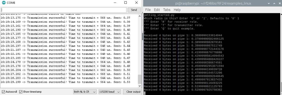
После выполнения вышеописанных настроек, получился следующий результат (время передачи пакета и пакет с числом 0.0, увеличивающимся с шагом 0.01):

Время передачи в среднем заняло всего 552 микросекунды
Передача данных между Arduino RF и Raspberry Pi
Далее пусть в качестве передатчика снова выступает микроконтроллер Arduino Nano RF, а в качестве приемника - Raspberry Pi 4 с модулем NRF24L01, подключённым по следующей схеме:

Для настройки Raspberry в качестве приемника, я выполнила следующие шаги:
Для удаленного подключения к Raspberry, определяю IP адрес Raspberry с помощью программы Aadvanced Ip scanner (альтернативный способ - через список подключенных устройств на странице роутера).
С помощью Putty, подключаюсь к Raspberry по ssh, указывая Ip адрес Raspberry и порт 22 (по умолчанию логин "pi", пароль "raspberry" ).
P.S. Для удобства работы через графический интерфейс, можно скачать программу VNCviewer, после чего ввести в консоль Raspberry команду vncserver.
В консоли Raspbrry для настройки SPI выполняю следующую команду
sudo raspi-config
В появившемся окне выбираю 5. Interfacting options -> SPI -> Enabledtparam=spi=on
Изначально, моя Raspberry Pi поставлялась в комплекте с дисплеем, подключаемым к тем же портам, что и NRFL01 модуль. После того, как дисплей убран, нужно отредактировать файл boot/config.txt , закоментировав строки, относящиеся к дисплею. В моем случае незакоментированной осталась только строка
dtparam=spi=on
Перезагружаюсь и обновляюсь
sudo reboot
sudo apt-get update
Далее устанавливаю библиотеку RF24 (например по инструкции на github или medium)
установка библиотиеки RF24 на Raspberry
Install prerequisites if there are any (MRAA, LittleWire libraries, setup SPI device etc)
Download the install.sh file from http://tmrh20.github.io/RF24Installer/RPi/install.sh
wget http://tmrh20.github.io/RF24Installer/RPi/install.shMake it executable
chmod +x install.shRun it and choose your options
./install.shRun an example from one of the libraries
cd rf24libs/RF24/examples_linuxEdit the gettingstarted example, to set your pin configuration
nano gettingstarted.cpp
make
sudo ./gettingstarted
В качестве примера также использую файл gettingstarted.py, после выполнения которого выбираю номер модуля "1" и режим "R".
код программы gettingstarted.py
""" A simple example of sending data from 1 nRF24L01 transceiver to another. This example was written to be used on 2 devices acting as 'nodes'. """ import sys import argparse import time import struct from RF24 import RF24, RF24_PA_LOW parser = argparse.ArgumentParser( description=doc, formatter_class=argparse.RawDescriptionHelpFormatter ) parser.add_argument( "-n", "--node", type=int, choices=range(2), help="the identifying radio number (or node ID number)" ) parser.add_argument( "-r", "--role", type=int, choices=range(2), help="'1' specifies the TX role. '0' specifies the RX role." ) ########### USER CONFIGURATION ########### See https://github.com/TMRh20/RF24/blob/master/pyRF24/readme.md Radio CE Pin, CSN Pin, SPI Speed CE Pin uses GPIO number with BCM and SPIDEV drivers, other platforms use their own pin numbering CS Pin addresses the SPI bus number at /dev/spidev<a>.<b> ie: RF24 radio(<ce_pin>, <a>*10+<b>); spidev1.0 is 10, spidev1.1 is 11 etc.. Generic: radio = RF24(22, 0) ################## Linux (BBB,x86,etc) ######################### See http://nRF24.github.io/RF24/pages.html for more information on usage See http://iotdk.intel.com/docs/master/mraa/ for more information on MRAA See https://www.kernel.org/doc/Documentation/spi/spidev for more information on SPIDEV using the python keyword global is bad practice. Instead we'll use a 1 item list to store our float number for the payloads sent/received payload = [0.0] def master(): """Transmits an incrementing float every second""" radio.stopListening() # put radio in TX mode failures = 0 while failures < 6: # use struct.pack() to packet your data into the payload # "<f" means a single little endian (4 byte) float value. buffer = struct.pack("<f", payload[0]) start_timer = time.monotonic_ns() # start timer result = radio.write(buffer) end_timer = time.monotonic_ns() # end timer if not result: print("Transmission failed or timed out") failures += 1 else: print( "Transmission successful! Time to Transmit: " "{} us. Sent: {}".format( (end_timer - start_timer) / 1000, payload[0] ) ) payload[0] += 0.01 time.sleep(1) print(failures, "failures detected. Leaving TX role.") def slave(timeout=6): """Listen for any payloads and print the transaction :param int timeout: The number of seconds to wait (with no transmission) until exiting function. """ radio.startListening() # put radio in RX mode start_timer = time.monotonic() while (time.monotonic() - start_timer) < timeout: has_payload, pipe_number = radio.available_pipe() if has_payload: # fetch 1 payload from RX FIFO buffer = radio.read(radio.payloadSize) # use struct.unpack() to convert the buffer into usable data # expecting a little endian float, thus the format string "<f" # buffer[:4] truncates padded 0s in case payloadSize was not set payload[0] = struct.unpack("<f", buffer[:4])[0] # print details about the received packet print( "Received {} bytes on pipe {}: {}".format( radio.payloadSize, pipe_number, payload[0] ) ) start_timer = time.monotonic() # reset the timeout timer print("Nothing received in", timeout, "seconds. Leaving RX role") # recommended behavior is to keep in TX mode while idle radio.stopListening() # put the radio in TX mode def set_role(): """Set the role using stdin stream. Timeout arg for slave() can be specified using a space delimiter (e.g. 'R 10' calls slave(10)) :return: - True when role is complete & app should continue running. - False when app should exit """ user_input = input( "*** Enter 'R' for receiver role.\n" "*** Enter 'T' for transmitter role.\n" "*** Enter 'Q' to quit example.\n" ) or "?" user_input = user_input.split() if user_input[0].upper().startswith("R"): if len(user_input) > 1: slave(int(user_input[1])) else: slave() return True elif user_input[0].upper().startswith("T"): master() return True elif user_input[0].upper().startswith("Q"): radio.powerDown() return False print(user_input[0], "is an unrecognized input. Please try again.") return set_role() if name == "main": args = parser.parse_args() # parse any CLI args # initialize the nRF24L01 on the spi bus if not radio.begin(): raise RuntimeError("radio hardware is not responding") # For this example, we will use different addresses # An address need to be a buffer protocol object (bytearray) address = [b"1Node", b"2Node"] # It is very helpful to think of an address as a path instead of as # an identifying device destination print(sys.argv[0]) # print example name # to use different addresses on a pair of radios, we need a variable to # uniquely identify which address this radio will use to transmit # 0 uses address[0] to transmit, 1 uses address[1] to transmit radio_number = args.node # uses default value from `parser` if args.node is None: # if '--node' arg wasn't specified radio_number = bool( int( input( "Which radio is this? Enter '0' or '1'. Defaults to '0' " ) or 0 ) ) # set the Power Amplifier level to -12 dBm since this test example is # usually run with nRF24L01 transceivers in close proximity of each other radio.setPALevel(RF24_PA_LOW) # RF24_PA_MAX is default # set the TX address of the RX node into the TX pipe radio.openWritingPipe(address[radio_number]) # always uses pipe 0 # set the RX address of the TX node into a RX pipe radio.openReadingPipe(1, address[not radio_number]) # using pipe 1 # To save time during transmission, we'll set the payload size to be only # what we need. A float value occupies 4 bytes in memory using # struct.pack(); "<f" means a little endian unsigned float radio.payloadSize = len(struct.pack("<f", payload[0])) # for debugging, we have 2 options that print a large block of details # (smaller) function that prints raw register values # radio.printDetails() # (larger) function that prints human readable data # radio.printPrettyDetails() try: if args.role is None: # if not specified with CLI arg '-r' while set_role(): pass # continue example until 'Q' is entered else: # if role was set using CLI args # run role once and exit master() if bool(args.role) else slave() except KeyboardInterrupt: print(" Keyboard Interrupt detected. Exiting...") radio.powerDown() sys.exit()
Получился аналогичный предыдущему пункту результат (на изображении показан вывод в IDE ArduinoStudio и Thonny):

В данном случае время передачи одного из пакетов значительно выше. Такая ситуация повторилась несколько раз.
Сравнение со связкой Arduino Leonardo + модуль NRF24L01
Данный краткий обзор был бы совсем кратким, не выполни я пример gettingstarted на стандартной связке Arduino + NRFL01 и Raspberry + NRFL01
Схема подключения NRFL01 к Arduino Nano изображена в посте выше. У меня не было под рукой Arduino Nano, но была Arduino Leonardo, у которой SPI пины вынесены сбоку платы.

Результат:
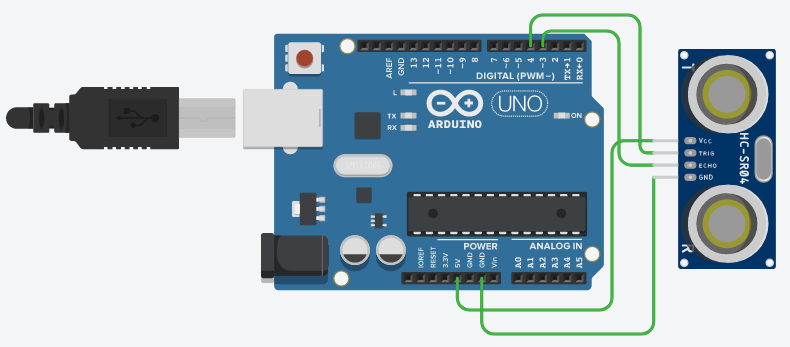
В конце поста, также покажу результат передачи информации о расстоянии до объекта, полученной с помощью имеющегося в наличии ультразвукового датчика, подключенного по схеме ( как подключается NRF24L01 модуль показано выше):
код Arduino US.ino
#include <SPI.h>
#include "nRF24L01.h"
#include "RF24.h"
#include <NewPing.h>
//static char send_payload[256];

#define TRIGGER_PIN 4      //Trig pin
#define ECHO_PIN  3        //Echo pin
#define MAX_DIST 400

const int min_payload_size = 4;
const int max_payload_size = 32;
const int payload_size_increments_by = 1;
int next_payload_size = min_payload_size;
float send_payload = 0.0;


NewPing sonar(TRIGGER_PIN, ECHO_PIN, MAX_DIST);
RF24 radio(7, 8); //
//const int role_pin = 5;

// Radio pipe addresses for the 2 nodes to communicate.
uint8_t address[][6] = {"1Node", "2Node"}; //
char receive_payload[max_payload_size + 1];
void setup()
{
  Serial.begin(115200);
  radio.begin();
  radio.enableDynamicPayloads();
  radio.setRetries(5, 15);
  radio.openWritingPipe(address[0]); //
  radio.openReadingPipe(1, address[1]); //
  radio.startListening();
}

void loop(void)
{
  int water_level = sonar.ping_cm();
  Serial.print("Sending Data :");
  Serial.print(water_level);
  Serial.println(" cm");
  //delay(1000);
  String water = String(water_level);

 radio.stopListening();
  send_payload = water_level;
  unsigned long start_timer = micros();                    // start the timer
  radio.write(&send_payload, sizeof(float));
  unsigned long end_timer = micros();                      // end the timer
  Serial.print(F("Time to transmit = "));
  Serial.print(end_timer - start_timer);                 // print the timer result
  Serial.print(F(" us. Sent: "));

}
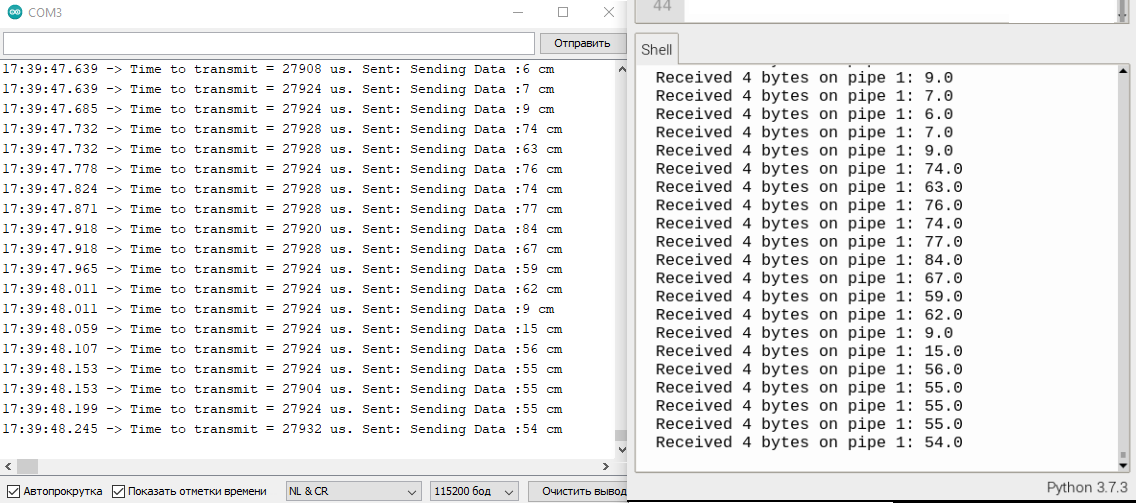
Результат выполнения показан ниже. Время передачи значительно выше. С ходу не хватает знаний понять, почему так вышло и как улучшить результат.
Заключение
К сожалению мне сходу не удалось найти в интернете подробных гайдов по работе с Arduino RF, поэтому пришлось пару недель повозиться. Знакомство с библиотекой Mirf как-то сразу не задалось. После многих попыток разобраться в теме, получился вот такой вот гайд. Оказалось, что работать с Arduino RF интересно и не так уж и трудно. Надеюсь что мой опыт пригодится новичкам и желающим построить какой-либо проект на базе Arduino RF. Также хочу выразить благодарность авторам постов про NRF24L01, которых набралось уже не мало :)

