Intro
Virtual Connect (VC) is an original networking device that was first introduced in HP BladeSystem c-Class infrastructure. Nowadays its performance and features have evolved for HPE Synergy, but it remains a distinctive converged module with some internal specifics to consider.
In this article I want to focus on traffic mirroring through Virtual Connect modules. Although an article on this topic is available on HPE Support Center, I would like to dig a bit deeper into some technical details and use cases.
Assumptions
First of all, I’d like to list several assumptions in order to avoid possible misinterpretations:
Virtual Connect terminology has changed after OneView introduction and I will use its latest version. However, the information is relevant for HP BladeSystem c-Class as well as for HPE Synergy.
Virtual Connect modules can be stacked and behave like a single logical device. All diagrams will represent single VC module, but stack behavior will be similar.
Several Virtual Connect uplinks can be aggregated with LACP into a single logical interface. All diagrams will represent single-port uplink, but LACP interface behavior will be similar.
Several VC Networks can be forwarded through a single uplink with VLAN tagging. All diagrams represent separate physical uplinks for each network for the sake of clarity.
Some figures show packets “captured” within VC modules. Standard 802.1Q tags are shown in these packets that is not completely accurate, as VC has its internal tagging mechanism. Such assumption is acceptable as internal VC tagging works like “standard” VLANs in a layer 2 device. You can find more details in VC traffic flow document.
Layer 2 basics
Before discussing traffic mirroring, I am going to describe two basic Virtual Connect mechanisms: port roles and Ethernet forwarding. This information will help us to understand why some configurations run well while other fail.
Virtual Connect is an advanced bridge, thus it has some specifics related to port roles and traffic forwarding. All VC ports are divided into two groups: uplinks and downlinks. Uplinks are used for connection to external switches or FC disk arrays (Flat SAN scenario) and downlinks are used for connection of Synergy Compute Modules or c-Class blades to the network.
All possible traffic flow options are shown on the Figure 1 below. An important thing to consider is that VC does not forward traffic from one uplink to another. That’s why you should not connect any end devices to uplink ports except supported Flat SAN configurations (visit HPE SPOCK for more details).

Due to layer 2 nature, VC forwarding mechanisms rely on MAC learning. Administrator configures separate networks that can be associated with VLANs, Fibre Channel fabric or tunnel traffic as-is. I will focus on pure Ethernet networks as their forwarding logic is quite standard:
Source MAC address from every received packet is being added to CAM table.
Broadcast, unknown unicast and multicast forwarding options are described in Table 1.
Table 1. VC BUM packet forwarding
# | Packet type | Received on | Forwarded to | Comments |
1 | Broadcast or unknown unicast | Uplink port | Downlinks within the same network | There is no uplink-to-uplink bridging |
2 | Broadcast or unknown unicast | Downlink | Downlinks and uplinks within the same network | N/A |
3 | Multicast | Uplink port | Downlinks within the same network | There is no uplink-to-uplink bridging. IGMP can be enabled to limit packet forwarding |
4 | Multicast | Downlink | Downlinks and uplinks within the same network | IGMP can be enabled to limit packet forwarding |
Unicast forwarding options are described in Table 2.
Table 2. VC unicast packet forwarding
# | Received on | Destination MAC | Action | Comments |
1 | Uplink port | Learned on another or same uplink | Packet dropped | There is no uplink-to-uplink bridging |
2 | Uplink port | Learned on a downlink | Forwarded to the downlink port | N/A |
3 | Downlink port | Learned on a uplink | Forwarded to the uplink port | N/A |
4 | Downlink port | Learned on another downlink | Forwarded to the downlink port where MAC address was learned | N/A |
5 | Downlink port | Learned on the same downlink | Packet dropped | N/A |
Only single uplink can be active for any network.
Traffic mirroring
Downlink-to-uplink traffic mirroring scenario can be fulfilled by standard Port Monitoring option configured in OneView. This process is documented in OneView User Guide.
But what about other options? Is it possible to receive mirrored traffic on Synergy Compute Module or c-Class Blade?
Support Center article mentioned in the beginning states that
The reason VC cannot perform this function is because VC does not have span or rspan capabilities. VC can only mirror downlink traffic to an uplink port using the 'Port Monitor' function.
The background for this limitation can be better understood by inspecting how VC handles mirrored traffic:
All source MAC addresses from this traffic are being learned on the uplink where it is received.
Broadcast and multicast traffic is being forwarded within configured VC network (see Table 1, rows 1 and 3).
Unknown unicast is also forwarded within configured VC network (see Table 1 row 1) until the destination MAC is learned on any port.
Due to significant role of broadcast in IPv4 and multicast in IPv6, all MAC addresses from mirrored traffic are soon learned on some port (typically uplink) and mirrored packets stop reaching mirror destination operating in promiscuous mode. Table 2 row 1 describes the most common scenario.
For example, mirroring source MAC address can be learned on some uplink after any ARP request from it.
So, there is no option to implement downlink-to-downlink or uplink-to-downlink traffic mirroring scenarios in Synergy frame or BladeSystem c-Class enclosure, isn’t it? Not really, there are two of them:
Using non-VC Ethernet interconnects: switches or pass-through modules.
It is the easiest way, but it lacks elegance. Additional cost and administrative burden can limit its applicability.ERSPAN implementation.
ERSPAN encapsulates mirrored traffic into GRE tunnel thus making it normal unicast traffic (see Table 2, rows 2 and 4). No “unneeded” MACs are learned on any port and no packets are dropped due to VC forwarding logic.
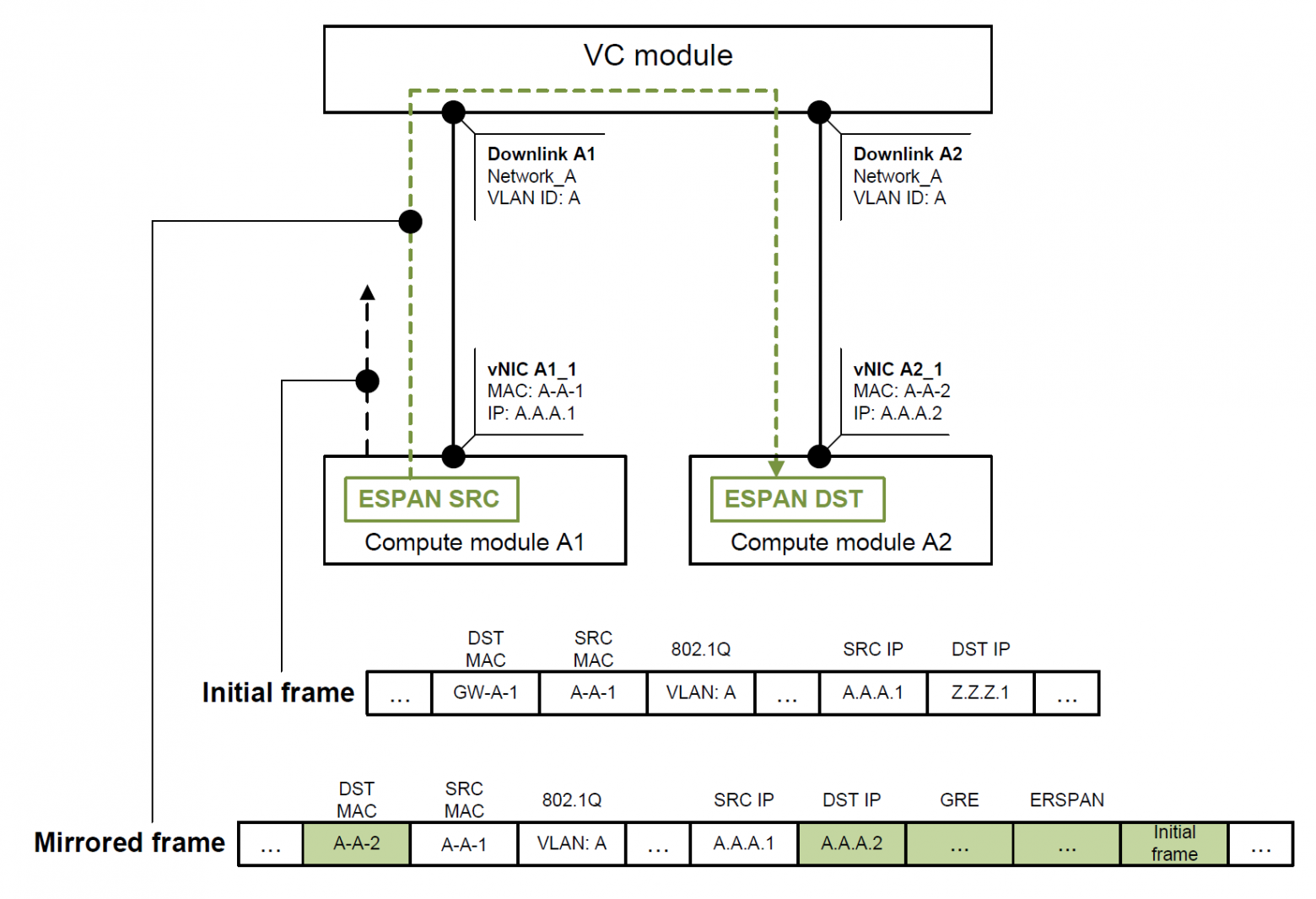
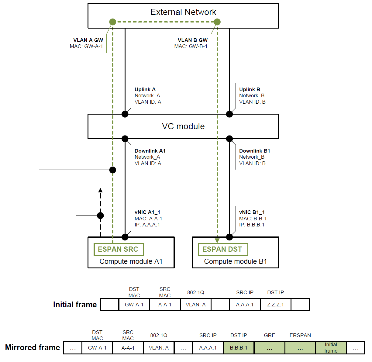
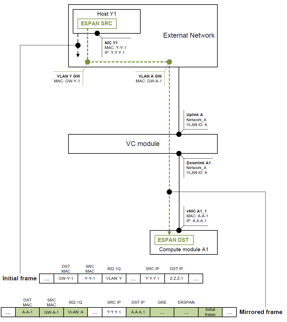
There are three ERSPAN implementation options that are listed in Table 3 and visualized on Figures 2, 3 and 4. All figures show initial and mirrored frames with highlighted header changes.
Table 3. ERSPAN implementation options
# | Mirror source | Mirror destination | Reference | Comment | Considerations |
1 | Downlink port | Downlink port within the same network | Figure 2 | Traffic is forwarded Internally within VC Network (table 2 row 4) | N/A |
2 | Downlink port | Downlink port within different network | Figure 3 | Traffic should be routed externally | Mirrored traffic consumes double uplink bandwidth |
3 | Outside network | Downlink port | Figure 4 | Unicast forwarding from uplink to downlink (table 2 row 2) | N/A |
You can also implement downlink-to-uplink traffic mirroring scenario with ERSPAN, but I'd recommend using Port Monitoring for it.

Initial packet should be routed to VLAN Z, thus DST MAC belongs to VLAN A gateway. Initial frame headers do not influence mirroring as the packet is being tunneled to ERSPAN destination (ERSPAN DST).

Traffic cannot be routed within Virtual Connect module, so ERSPAN goes through the uplinks before and after the routing. This behavior may prevent using such scenario with intensive traffic flow mirroring as it may waste plenty of uplink bandwidth or even lead to a congestion.

This is likely the most common scenario. Example shows initial packet being routed between VLANs Y and Z, while mirrored packet is routed between VLANs Y and A before it enters Virtual Connect module.
ERSPAN feature can be enabled in many popular operating systems and hypervisors (e.g., Linux, Windows and VMware), thus making them potential traffic sources. Mirrored traffic can be inspected with Wireshark using embedded ERSPAN dissector or decapsulated by open-source or commercial software.
Resume
From Ethernet perspective Virtual Connect is an advanced Layer 2 bridge.
Downlink traffic can be mirrored to uplink port using standard Port Monitoring function.
ERSPAN is a viable option for downlink-to-downlink or uplink-to-downlink mirroring scenarios.