AHURATUS Smart Home Voice Assistant
Developed by Ehsan Shaghaei
Innopolis University
AHURATUS Scientific Club.

Introduction
AHURATUS Smart Home Voice Assistant is an IOT device developed in order to control other home devices by voice detection. Note: This device is made ONLY for academic purposes.
Approach
Description
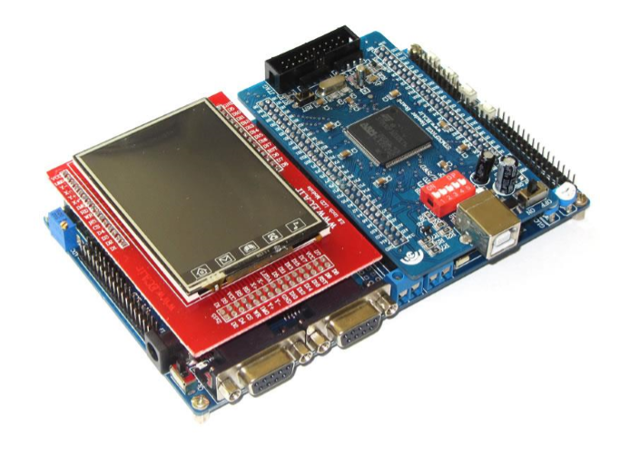
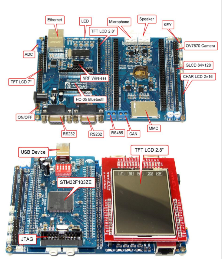
"AHURATUS Smart Home Voice Assistant" uses an ARM Cortex-M3 process for running the instructions as well as several peripheral devices in order to decrease the complexity of data bus and RF-Circuit calculations.
Bill of Materials
| # | Component Name | Role | Technical Document links |
|---|---|---|---|
| 1 | STM32F103ZET6 | Process and Control | Datasheet |
| 2 | HC-05 Bluetooth Module | Bluetooth Radio Connection | Datasheet |
| 3 | 220-5V AC-DC Adapter | Powering the circuit | Datasheet |
| 4 | LED or Mosfets or Relays | To System Output | Datasheet |
Workbench and Softwares
| # | Software Name | Role | Links and refrences |
|---|---|---|---|
| 1 | STM32CubeIDE | IDE for Coding our instruction | Link |
| 2 | GNU-ARM | C-Compiler for ARM processors | Link |
| 3 | Jlink | Programmer and Debugger | Link |
| 4 | HERCULES | SerialPort Monitoring Software | Link |
| 5 | Arduino Voice Control | Android Application to send data to our device | Link |

Details
We use HAL drivers which were provided by the processor manufacture in order to reduce the complexity of fault checking and straight forward usage of peripherals. We use HC-05 in order to receive data from our user via a wireless connection by setting the module settings trough the following AT command:
Transmit: AT+UART = 115200, 0, 0
Response: OK
_ Note: In order to apply AT Commands you need to connect the KEY pin to the HIGH level.
by using STM32CubeIDE we set the peripheral registers as follows:
- UART2 (HC-05 Serial Port):
 huart2.Instance = USART2;
  huart2.Init.BaudRate = 115200;
  huart2.Init.WordLength = UART_WORDLENGTH_8B;
  huart2.Init.StopBits = UART_STOPBITS_1;
  huart2.Init.Parity = UART_PARITY_NONE;
  huart2.Init.Mode = UART_MODE_TX_RX;
  huart2.Init.HwFlowCtl = UART_HWCONTROL_NONE;
  huart2.Init.OverSampling = UART_OVERSAMPLING_16;
  if (HAL_UART_Init(&huart2) != HAL_OK)
  {
    Error_Handler();
}- UART1 (Monitoring Serial Port Trough RS-232 Standard Port):
 huart1.Instance = USART1;
  huart1.Init.BaudRate = 115200;
  huart1.Init.WordLength = UART_WORDLENGTH_8B;
  huart1.Init.StopBits = UART_STOPBITS_1;
  huart1.Init.Parity = UART_PARITY_NONE;
  huart1.Init.Mode = UART_MODE_TX_RX;
  huart1.Init.HwFlowCtl = UART_HWCONTROL_NONE;
  huart1.Init.OverSampling = UART_OVERSAMPLING_16;
  if (HAL_UART_Init(&huart1) != HAL_OK)
  {
    Error_Handler();
}- DMA Channels 11, 15 and 16 (Direct Memory Access for UART2 RX and UART1 RX and UART1 TX respectively.):
 /* DMA controller clock enable */
  __HAL_RCC_DMA1_CLK_ENABLE();

  /* DMA interrupt init */
  /* DMA1_Channel1_IRQn interrupt configuration */
  HAL_NVIC_SetPriority(DMA1_Channel1_IRQn, 0, 0);
  HAL_NVIC_EnableIRQ(DMA1_Channel1_IRQn);
  /* DMA1_Channel5_IRQn interrupt configuration */
  HAL_NVIC_SetPriority(DMA1_Channel5_IRQn, 0, 0);
  HAL_NVIC_EnableIRQ(DMA1_Channel5_IRQn);
  /* DMA1_Channel6_IRQn interrupt configuration */
  HAL_NVIC_SetPriority(DMA1_Channel6_IRQn, 0, 0);
  HAL_NVIC_EnableIRQ(DMA1_Channel6_IRQn);
Furthermore, we set the GPIO modes as following in order to Drive our LEDs or other Devices.
  /* GPIO Ports Clock Enable */
  __HAL_RCC_GPIOE_CLK_ENABLE();
  __HAL_RCC_GPIOC_CLK_ENABLE();
  __HAL_RCC_GPIOF_CLK_ENABLE();
  __HAL_RCC_GPIOA_CLK_ENABLE();
  __HAL_RCC_GPIOB_CLK_ENABLE();
  __HAL_RCC_GPIOD_CLK_ENABLE();
  __HAL_RCC_GPIOG_CLK_ENABLE();

  /*Configure GPIO pin Output Level */
  HAL_GPIO_WritePin(GPIOE, GPIO_PIN_5, GPIO_PIN_RESET);

  /*Configure GPIO pin Output Level */
  HAL_GPIO_WritePin(GPIOF, LED3_Pin|GPIO_PIN_7|LED1_Pin, GPIO_PIN_RESET);

  /*Configure GPIO pin Output Level */
  HAL_GPIO_WritePin(GPIOB, LED4_Pin|GPIO_PIN_2, GPIO_PIN_RESET);

  /*Configure GPIO pin Output Level */
  HAL_GPIO_WritePin(GPIOG, GPIO_PIN_6|LED2_Pin|GPIO_PIN_11, GPIO_PIN_RESET);

  /*Configure GPIO pin : PE2 */
  GPIO_InitStruct.Pin = GPIO_PIN_2;
  GPIO_InitStruct.Mode = GPIO_MODE_IT_RISING_FALLING;
  GPIO_InitStruct.Pull = GPIO_NOPULL;
  HAL_GPIO_Init(GPIOE, &GPIO_InitStruct);

  /*Configure GPIO pins : PE3 PE4 PE6 */
  GPIO_InitStruct.Pin = GPIO_PIN_3|GPIO_PIN_4|GPIO_PIN_6;
  GPIO_InitStruct.Mode = GPIO_MODE_INPUT;
  GPIO_InitStruct.Pull = GPIO_NOPULL;
  HAL_GPIO_Init(GPIOE, &GPIO_InitStruct);

  /*Configure GPIO pin : PE5 */
  GPIO_InitStruct.Pin = GPIO_PIN_5;
  GPIO_InitStruct.Mode = GPIO_MODE_OUTPUT_PP;
  GPIO_InitStruct.Pull = GPIO_NOPULL;
  GPIO_InitStruct.Speed = GPIO_SPEED_FREQ_LOW;
  HAL_GPIO_Init(GPIOE, &GPIO_InitStruct);

  /*Configure GPIO pins : LED3_Pin PF7 LED1_Pin */
  GPIO_InitStruct.Pin = LED3_Pin|GPIO_PIN_7|LED1_Pin;
  GPIO_InitStruct.Mode = GPIO_MODE_OUTPUT_PP;
  GPIO_InitStruct.Pull = GPIO_NOPULL;
  GPIO_InitStruct.Speed = GPIO_SPEED_FREQ_LOW;
  HAL_GPIO_Init(GPIOF, &GPIO_InitStruct);

  /*Configure GPIO pin : PA0 */
  GPIO_InitStruct.Pin = GPIO_PIN_0;
  GPIO_InitStruct.Mode = GPIO_MODE_INPUT;
  GPIO_InitStruct.Pull = GPIO_NOPULL;
  HAL_GPIO_Init(GPIOA, &GPIO_InitStruct);

  /*Configure GPIO pins : LED4_Pin PB2 */
  GPIO_InitStruct.Pin = LED4_Pin|GPIO_PIN_2;
  GPIO_InitStruct.Mode = GPIO_MODE_OUTPUT_PP;
  GPIO_InitStruct.Pull = GPIO_NOPULL;
  GPIO_InitStruct.Speed = GPIO_SPEED_FREQ_LOW;
  HAL_GPIO_Init(GPIOB, &GPIO_InitStruct);

  /*Configure GPIO pin : PB10 */
  GPIO_InitStruct.Pin = GPIO_PIN_10;
  GPIO_InitStruct.Mode = GPIO_MODE_AF_PP;
  GPIO_InitStruct.Speed = GPIO_SPEED_FREQ_HIGH;
  HAL_GPIO_Init(GPIOB, &GPIO_InitStruct);

  /*Configure GPIO pin : PB11 */
  GPIO_InitStruct.Pin = GPIO_PIN_11;
  GPIO_InitStruct.Mode = GPIO_MODE_INPUT;
  GPIO_InitStruct.Pull = GPIO_NOPULL;
  HAL_GPIO_Init(GPIOB, &GPIO_InitStruct);

  /*Configure GPIO pins : PG6 LED2_Pin PG11 */
  GPIO_InitStruct.Pin = GPIO_PIN_6|LED2_Pin|GPIO_PIN_11;
  GPIO_InitStruct.Mode = GPIO_MODE_OUTPUT_PP;
  GPIO_InitStruct.Pull = GPIO_NOPULL;
  GPIO_InitStruct.Speed = GPIO_SPEED_FREQ_LOW;
  HAL_GPIO_Init(GPIOG, &GPIO_InitStruct);

  /*Configure GPIO pin : PG8 */
  GPIO_InitStruct.Pin = GPIO_PIN_8;
  GPIO_InitStruct.Mode = GPIO_MODE_IT_RISING;
  GPIO_InitStruct.Pull = GPIO_NOPULL;
  HAL_GPIO_Init(GPIOG, &GPIO_InitStruct);
Finally, we write the following code in c main() function in order to execute our command decoding algorithm :
HAL_UART_Transmit(&huart1,"Ping->> AHURATUS VOICE ASSISTANT\r\n", sizeof("Ping->> AHURATUS VOICE ASSISTANT\r\n"), 1);
int i;
    for (i=0; i<100;i++){
          data[i] = '\0';
      }
HAL_UART_Receive_DMA(&huart2, data, sizeof(data));

   while (1)
  {
     if(strlen(data)>2){
         if(strcasecmp( data,"Hey")==0){
                  HAL_UART_DMAStop(&huart2);
                  HAL_UART_Transmit(&huart1, "How can I help you ?\r\n", sizeof("How can I help you ?\r\n"), 100);//Users Signal Receieved!
                  int i;
                  for (i=0; i<100;i++){
                      data[i] = '\0';
                  }
                  HAL_UART_Receive_DMA(&huart2, data, sizeof(data));// Polling for new data
                  int FLG = 1;
                  while(!strlen(data)){

                      if(FLG){
                          HAL_UART_Transmit(&huart1, "Polling for Command ...\r\n", sizeof("Polling for Command ...\r\n"), 1);
                      }
                     FLG= 0;
                     //wait...
                  }
                  HAL_Delay(200);//short delay to recieve the rest of data;

                  if(   (!strcasecmp(data,"turn on light one"))
                          ||(!strcasecmp(data,"turn on light 1")) ){
                    HAL_GPIO_WritePin(LED1_GPIO_Port, LED1_GPIO_Port,GPIO_PIN_SET);
                            HAL_UART_Transmit(&huart1, "Light 1 Turned ON\r\n", sizeof("Light 1 Turned ON\r\n"), 1);
                  }else if( (!strcasecmp(data,"turn off light one"))
                          ||(!strcasecmp(data,"turn off light 1")) ){
                    HAL_GPIO_WritePin(LED1_GPIO_Port, LED1_GPIO_Port,GPIO_PIN_RESET);
                            HAL_UART_Transmit(&huart1,  "Light 1 Turned OFF\r\n", sizeof("Light 1 Turned OFF\r\n"), 1);
                  }else if( (!strcasecmp(data,"turn on light two"))
                          ||(!strcasecmp(data,"turn on light 2")) ){
                    HAL_GPIO_WritePin(LED2_GPIO_Port, LED2_GPIO_Port,GPIO_PIN_SET);
                            HAL_UART_Transmit(&huart1,  "Light 2 Turned ON\r\n", sizeof("Light 2 Turned ON\r\n"), 1);
                  }else if( (!strcasecmp(data,"turn off light two"))
                          ||(!strcasecmp(data,"turn off light 2")) ){
                    HAL_GPIO_WritePin(LED2_GPIO_Port, LED2_GPIO_Port,GPIO_PIN_RESET);
                            HAL_UART_Transmit(&huart1,  "Light 2 Turned OFF\r\n", sizeof("Light 2 Turned OFF\r\n"), 1);
                  }else if( (!strcasecmp(data,"turn on light three"))
                          ||(!strcasecmp(data,"turn on light 3")) ){
                    HAL_GPIO_WritePin(LED3_GPIO_Port, LED3_GPIO_Port,GPIO_PIN_SET);
                            HAL_UART_Transmit(&huart1,  "Light 3 Turned ON\r\n", sizeof("Light 3 Turned ON\r\n"), 1);
                  }else if( (!strcasecmp(data,"turn off light three"))
                          ||(!strcasecmp(data,"turn off light 3")) ){
                    HAL_GPIO_WritePin(LED3_GPIO_Port, LED3_GPIO_Port,GPIO_PIN_RESET);
                            HAL_UART_Transmit(&huart1, "Light 3 Turned OFF\r\n", sizeof("Light 3 Turned OFF\r\n"), 1);
                  }else if( (!strcasecmp(data,"turn on light four"))
                          ||(!strcasecmp(data,"turn on light 4")) ){
                    HAL_GPIO_WritePin(LED4_GPIO_Port, LED4_GPIO_Port,GPIO_PIN_SET);
                            HAL_UART_Transmit(&huart1, "Light 4 Turned ON\r\n", sizeof("Light 4 Turned ON\r\n"), 1);

                  }else if( (!strcasecmp(data,"turn off light four"))
                          ||(!strcasecmp(data,"turn off light 4")) ){
                    HAL_GPIO_WritePin(LED4_GPIO_Port, LED4_GPIO_Port,GPIO_PIN_RESET);
                            HAL_UART_Transmit(&huart1, "Light 4 Turned OFF\r\n", sizeof("Light 4 Turned OFF\r\n"), 1);
                  }

                  }else{
                            HAL_UART_Transmit(&huart1, "ERROR-> INVALID Command\r\n", sizeof("ERROR-> INVALID Command\r\n"), 1);
                  }
                  HAL_UART_DMAStop(&huart2);
                  for (i=0; i<100;i++){ data[i] = '\0'; }//makes the buffer empty
                  HAL_UART_Receive_DMA(&huart2, data, sizeof(data));

              }

     }
Afterward, we use an android device to connect to our system by Bluetooth. we use "Arduino Voice Control" application in order to send voice to our system.
by Keyword "HEY" our system polls for the next commands and follows your voice commands as mentioned above.
Conclusion
"AHURATUS Smart Home Voice Assistant" project can be used in order to have a simple and cheap functional smart home device by a few simple modifications in the circuit; such as:
- Using a MOSFET and an AC Isolation Circuit to control devices with AC working voltages
- Using Pulse Width Modulation (PWM) in order to have more control over the output
- Use TRIAC to have a adjustable light level setter
- Design a better application to have better interaction with user
- use Kinect or other Motion Detection Devices to measure make the device compatible with users gestures.
Regards,
Ehsan Shaghaei
Contact to me

