Software component developers tend to be far removed from the end users of the products in which their components are employed. Recently, however, we connected directly with a KOMPAS-3D MCAD user to solve an issue involving mold design. It seems that 3D models were being exported incorrectly to data exchange formats like STP, X_T, and SAT. The cause, unhappily for us, turned out to be in our С3D Modeler geometric modeling kernel. Here is how we solved the problem, quickly.

Aleksei Grekov is the lead design engineer at Sverdlovsk Instrument Plant. He has designed molds for 36 years, for the last 15 with KOMPAS-3D. As such, he is extremely conscientious. He takes responsibility for his work and monitors the state of his creations right through to production. For this reason, you often find Aleksei Grekov on the plant's production floor.
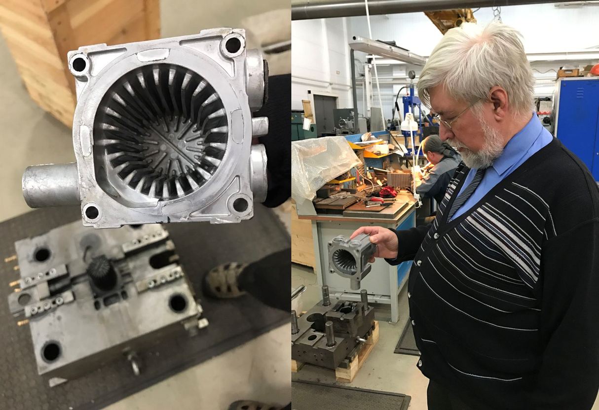

In addition to manufacturing its own products, the factory produces molds for outside customers. One such customer order resulted in the Sverdlovsk factory requesting support for a puzzling problem, which ended up with our C3D Labs tech support. Sverdlovsk Instrument Plant had to deliver a 3D model in a data exchange format, because the customer did not use KOMPAS-3D. Following the export and import procedure, the result ended up as a surface instead of as a solid body. Surfaces cannot be used to make molds, and so the customer wasn't going to be able to use the 3D model.
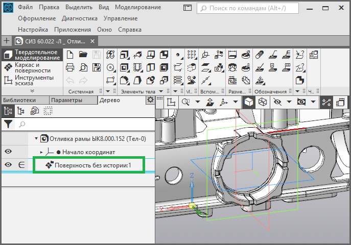
Incorrect surface resulting from filleting bug
The issue arose when the design department deployed a new version of KOMPAS-3D. The suspicions of employees were aroused after, as they put it, “not only did they change the interface, but they also wrecked the export function!”
 Aleksei Grekov recounts what happened:
First, developers proposed a workaround to properly form the model: change the geometry to align the edges. As it turned out, changing the geometry was not an option, as precision was of the utmost importance. The proposed workaround didn't work.
Detailed diagnostics showed that the model was being built with a defect that did not prevent it from being edited by KOMPAS-3D, yet made it incompatible with data exchange.
The clue to the problem came from observing that the closed shell opened upon going through translation. The cause was the addition of boundary edges that stemmed from a Boolean operation. The CAD designer had traced a contour on a face, extruded it, and then unioned it with the parent body. But the contour slightly exceeded the size of the face because of the peculiarities of the constraints that were applied.
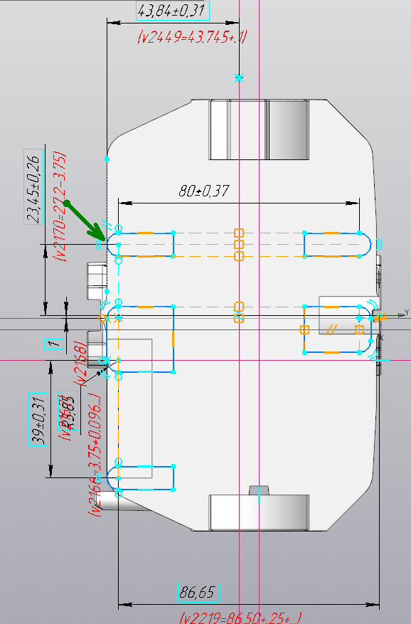
The arrow indicates a contour exceeding the size of the face
That the contour stuck out beyond the edges was in itself not necessarily a problem. The issue arose because the contour stuck out by just a little, by an amount equivalent to the tolerance. Hence, the Boolean operation proceeded along the branch that bypassed face creation. Small gaps are not as big a problem to kernel mathematics as are faces of similar sizes – this is true for modeling algorithms but not, as it turned out, for model exchange. Having determined the problem, our programmers resolved it by tuning the criteria that decided whether or not to create faces.
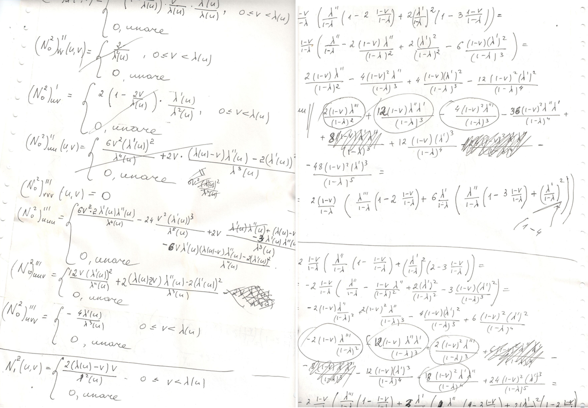
Mathematical solution to the export problem
But then another source of the boundary edges bug was found. The fillet operation's input parameters involve the fillet radius, plus a chain of edges to be replaced by new faces. Often, a fillet operation is not strictly local: sometimes it affects not only the faces that touch the edges of the fillet chain, but others as well. Difficult situations can arise at the ends of open chains, because constructing fillets correctly requires the modification of the faces of all the edges that adjoin outer vertices.
If a fillet's radius is larger than a face's lateral dimension (with respect to the edge), then the faces that are not neighbors also need modification. Certain cases were processed by the regular functions designed for modifying faces adjoining outer vertices; other faces were processed separately as special cases. As a result of the request from Sverdlovsk Instrument Plant, we increased the number of special cases that are processed successfully.
The new mathematical solution was immediately added to the C3D Modeler geometric modeling kernel and then to KOMPAS-3D v17 as an express update, which was delivered to the designers at Sverdlovsk Instrument Plant. The only thing for them to do was to apply KOMPAS-3D’s “Rebuild” command to the model, export it to the exchange format, and then check the result by reimporting the file.
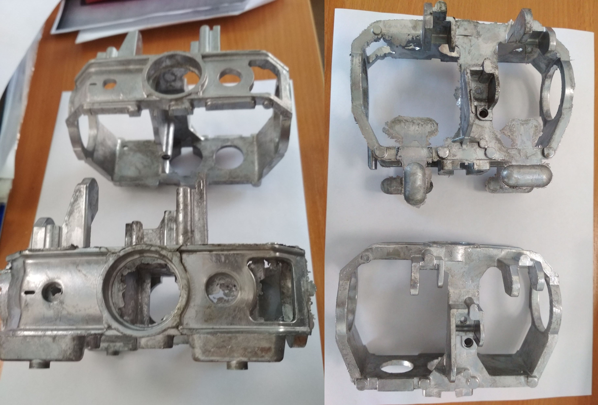
Aleksei Grekov reports on the result: “Our factory produced an extremely complex mold for casting, on which we had spent a long time working. This project involved a series of requests for assistance, which were answered successfully. Today, the gear produced by this project was tested and the results are positive. All this work was worth the time and effort, and I attach photographs of the final result. Many thanks to all of your staff!”

 by Alexander Spivakov, Head of C3D Converter Development at C3D Labs
Request an Evaluation of C3D Toolkit
P.S. it is crosspost.

Mold Under Threat
Aleksei Grekov is the lead design engineer at Sverdlovsk Instrument Plant. He has designed molds for 36 years, for the last 15 with KOMPAS-3D. As such, he is extremely conscientious. He takes responsibility for his work and monitors the state of his creations right through to production. For this reason, you often find Aleksei Grekov on the plant's production floor.


In addition to manufacturing its own products, the factory produces molds for outside customers. One such customer order resulted in the Sverdlovsk factory requesting support for a puzzling problem, which ended up with our C3D Labs tech support. Sverdlovsk Instrument Plant had to deliver a 3D model in a data exchange format, because the customer did not use KOMPAS-3D. Following the export and import procedure, the result ended up as a surface instead of as a solid body. Surfaces cannot be used to make molds, and so the customer wasn't going to be able to use the 3D model.

Incorrect surface resulting from filleting bug
The issue arose when the design department deployed a new version of KOMPAS-3D. The suspicions of employees were aroused after, as they put it, “not only did they change the interface, but they also wrecked the export function!”
 Aleksei Grekov recounts what happened:
Our customer didn't use KOMPAS-3D and they needed the model not just for viewing but also for shopfloor processing and then assembly. KOMPAS Viewer would have been sufficient if the model only needed to be viewed. The export/import function had to work correctly to provide the solid model and not a surface one. In the previous versions of KOMPAS-3D, the translation function worked better, and we rarely encountered problems creating intermediate formats.After analyzing the issue, the KOMPAS-3D developers realized that the crux of the problem lay in some mathematics. From the outside, the mold appeared to be closed and KOMPAS-3D treated it as if it was. In reality, the edges of the model were not aligned, so they had split, which turned the solid into a surface model. Specific expertise was required to solve the issue as the standard algorithms of the С3D Modeler geometric modeling kernel (upon which KOMPAS-3D is based) were unable to solve the problem.
First, developers proposed a workaround to properly form the model: change the geometry to align the edges. As it turned out, changing the geometry was not an option, as precision was of the utmost importance. The proposed workaround didn't work.
Mold Formula
Detailed diagnostics showed that the model was being built with a defect that did not prevent it from being edited by KOMPAS-3D, yet made it incompatible with data exchange.
The clue to the problem came from observing that the closed shell opened upon going through translation. The cause was the addition of boundary edges that stemmed from a Boolean operation. The CAD designer had traced a contour on a face, extruded it, and then unioned it with the parent body. But the contour slightly exceeded the size of the face because of the peculiarities of the constraints that were applied.

The arrow indicates a contour exceeding the size of the face
That the contour stuck out beyond the edges was in itself not necessarily a problem. The issue arose because the contour stuck out by just a little, by an amount equivalent to the tolerance. Hence, the Boolean operation proceeded along the branch that bypassed face creation. Small gaps are not as big a problem to kernel mathematics as are faces of similar sizes – this is true for modeling algorithms but not, as it turned out, for model exchange. Having determined the problem, our programmers resolved it by tuning the criteria that decided whether or not to create faces.

Mathematical solution to the export problem
But then another source of the boundary edges bug was found. The fillet operation's input parameters involve the fillet radius, plus a chain of edges to be replaced by new faces. Often, a fillet operation is not strictly local: sometimes it affects not only the faces that touch the edges of the fillet chain, but others as well. Difficult situations can arise at the ends of open chains, because constructing fillets correctly requires the modification of the faces of all the edges that adjoin outer vertices.
If a fillet's radius is larger than a face's lateral dimension (with respect to the edge), then the faces that are not neighbors also need modification. Certain cases were processed by the regular functions designed for modifying faces adjoining outer vertices; other faces were processed separately as special cases. As a result of the request from Sverdlovsk Instrument Plant, we increased the number of special cases that are processed successfully.
In The Morning in C3D Kernel, By Evening in KOMPAS-3D
The new mathematical solution was immediately added to the C3D Modeler geometric modeling kernel and then to KOMPAS-3D v17 as an express update, which was delivered to the designers at Sverdlovsk Instrument Plant. The only thing for them to do was to apply KOMPAS-3D’s “Rebuild” command to the model, export it to the exchange format, and then check the result by reimporting the file.
Aleksei Grekov reports on the result: “Our factory produced an extremely complex mold for casting, on which we had spent a long time working. This project involved a series of requests for assistance, which were answered successfully. Today, the gear produced by this project was tested and the results are positive. All this work was worth the time and effort, and I attach photographs of the final result. Many thanks to all of your staff!”


 by Alexander Spivakov, Head of C3D Converter Development at C3D Labs
Video: Introducing C3D Toolkit for Engineering Software Development
Request an Evaluation of C3D Toolkit
P.S. it is crosspost.