Introduction
We are the first year students studying Computer Science in Innopolis University and we would like to share our experience in developing a Verilog program to create the coolest (well, at least, the loudest) rotary encoder ever on an FPGA board.
In this article, you will find a wonderful story about our project, the hardware, software we used and some background theory regarding rotary encoder and creating sounds in FPGA’s buzzer. Finally, we will provide a link to a github repository where a reader can access the source code. We hope you will like the project and it will inspire you to make something similar.
So, let’s start!
Hardware and Software

- Cyclone IV FPGA Device support for Quartus Prime
- Quartus Prime Lite Edition
- A rotary encoder from Arduino kit
- ModelSim*-Intel FPGA(for debugging only)
- Wires from Arduino kit
A brief story
A long time ago in a galaxy far away a group of students (us) decided to get closer to a hardware. Computer Architecture course gave us a great opportunity to make a project on FPGA boards. After some discussions, we chose to implement a system with a rotary encoder. We accomplished the task but it was not enough to satisfy our desires, so we decided to upgrade our project by turning it into a musical instrument using a keyboard and a board’s buzzer to play different notes. However, it turned out that FPGA’s PS/2 port is dead.
Eventually, we end up with writing a simple melody that is played when the button is pressed.
Musical Box
We can distinguish one note from another by frequencies of their sound waves. Hence, to make a buzzer play different notes we need to make it generate sound waves with different frequencies.
We decided to work with square waves as they are pretty easy to implement.
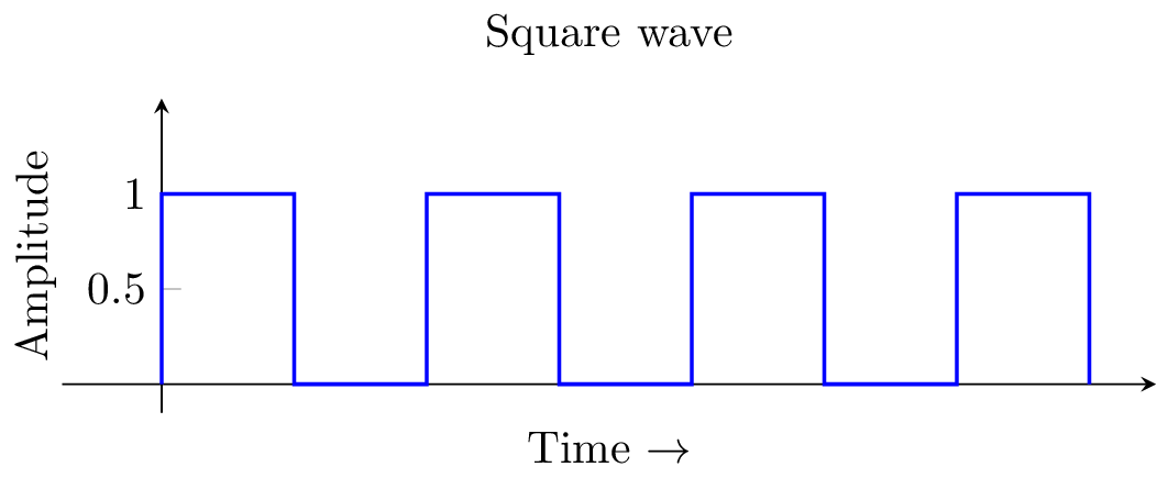
A square wave is a signal that changes its state between high and low. The main idea of a square wave is that the time when the signal at the high state and the time when the signal at the low state are the same. To generate a square wave you need to turn on an I/O, wait for x amount of time, turn off the I/O, wait from x amount of time, and repeat those actions as many times as you need.

This picture was taken from here.
Cyclone IV has a clock generator with frequency 50 MHz. Using the definition of a square wave, it’s not that hard to derive the following formula:
x = (50*10^6)/(2*n)
where n is the desired frequency in Hz and x is a number of clock cycles we need to wait before changing the state from high to low and vice versa.
To make a buzzer generate waves with frequency n Hz we implemented a clock divider.
More about clock divider and square waves you can read here.
Another but:
Due to the low quality of buzzers it is not possible to play notes with low frequencies. So, we used the ones from F# of the 4th octave to C# of the 5th octave.
It is a flowchart that shows a logic of the musical box.

Rotary Encoder
How does the rotary encoder work?
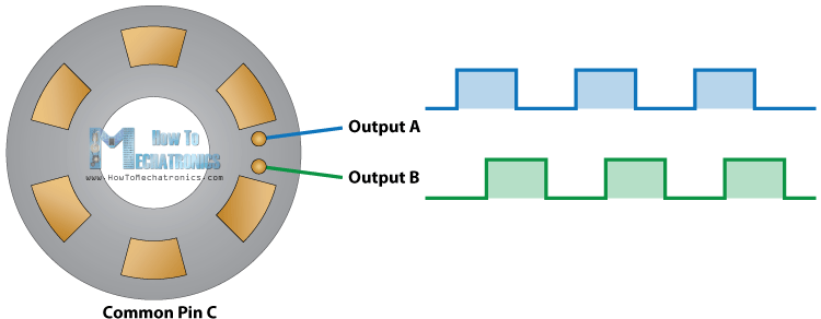
It is a thing made of a circle with conductor plates and two analogue sensors.
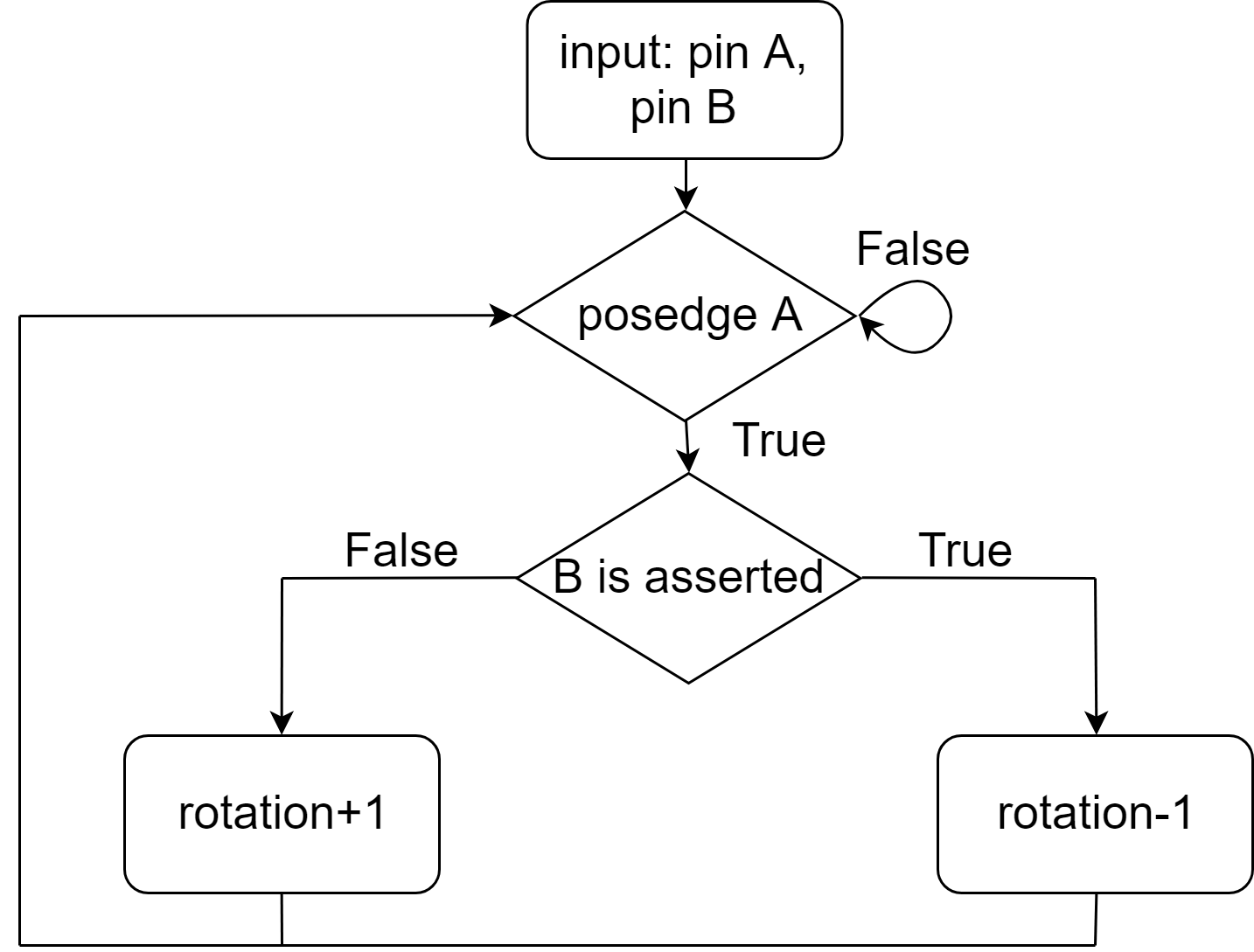
As you can see from a picture when you turn the rotary encoder, one of the sensors touches the plate first and goes from low to high. So, at that moment we can know, whether we are turning the encoder clockwise or counterclockwise. The idea is the following: we will look at sensor B every time when sensor A goes from low to high. If at that moment B is asserted, the encoder was turned clockwise, otherwise, counterclockwise. Now, by the word rotation, we mean turning the encoder on one section.

(the picture was stolen from howtomechatronics.com)
It is a flowchart that shows a logic of the rotary encoder

Also, we want to output the angle of rotation onto the 8-segment display. Our encoder has 20 segments, so rotation on one segment is equal to a rotation on the angle of 18 and the formula we use is:
angle = (number of rotations mod 20) * 18
Materials
The code of our project is here.
Here and here are the videos of the rotary encoder and the musical box.
Authors: Amina Miftahova, Kamil Kamaliev, Lev Svalov.
