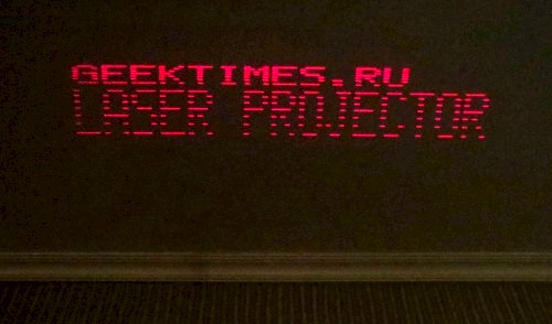
Let’s find out how to make a simple enough laser projector out of electronics you can find at home.
If you have dabbled into microchip photographing before, then this article will probably not offer much to you. But if you want to get into it, but don’t know where to start, then it’s exactly for you.
Before we start, a fair warning: while the procedure is quite entertaining, at first it’ll probably be physically painful. The chemicals used during the process are toxic, so please handle them carefully – that way it’ll still hurt, but less so. Also, if you have even a slight amount of common sense, conduct the procedure in a fully-equipped chemical laboratory under supervision of trained professionals: we’ve had to deal with people who tried to do it at home immediately after reading the guide. And finally: if you don’t know whether you need to pour acid into water or water into acid without a Google search and don’t realize what this lack of knowledge will entail – stop reading this immediately and go to a chemistry 101 course in a local college or something.

Space exploration was always fascinating, and recent developments have reignited the interest to the heights never seen since the last man stood on the Moon. People argue about Mars exploration and features of spaceships as their grandparents would’ve done if the internet existed fifty years ago. I’m an electronics engineer working in the aerospace industry, so I know a thing or two about the technical background of this stuff — and I see that these things aren’t common knowledge, and people often have significantly skewed ideas about the reasons behind many things and decisions. Namely, I’d love to speak of some misconceptions about radiation hardened integrated circuits and the means of protection from radiation-induced damage.

I made the “electric” designer of… cardboard. Alas, the project still remains at the prototype stage, not developing into an industrial “physical” look and is waiting for its time (and investor).
But I decided to go further — once we started making cardboard, we’ll bring the situation to its logical conclusion — we’ll make a complete cardboard board game, but with an electric setting and a learning effect. There were a lot of options — starting from a simple “walker” and ending with Ameritrash from a zombie with electron movement and vicious short circuits and swollen capacitors.
As a result, I decided to dwell on a logical abstract, since the schematics of electrical circuits are very suitable for it. Said and done — as a result of the first iteration, the game “Circuit” was born.

Gowin has clear advantages over Xilinx in the educational FPGA board market: Gowin boards are several times less expensive, the synthesis speed is several times faster, and the EDA package is two orders of magnitude smaller: we are talking about 1G versus 100G disk space. Of course, Xilinx is still the king of high-end prototyping boards that cost $10K-100K, but for the students such boards are irrelevant; such boards are for ASIC design companies. A beginning EE student needs a board for less than $100, and Gowin not only fits the bill but also covers all the needs, specifically:
 Saluting my LED lamp fans!
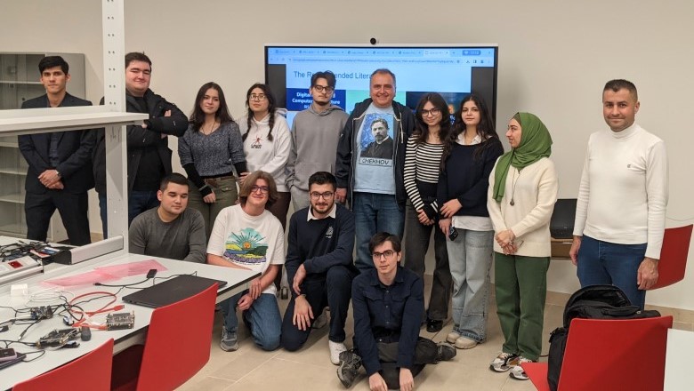
Last week I was doing a seminar on SystemVerilog, ASIC and FPGA at ADA University in Baku, Azerbaijan. I will replicate the last two sessions of this seminar, on RISC-V CPU simulation and synthesis, at the Verilog Meetups on March 3 and March 10 at Hacker Dojo, Mountain View, California. For this reason I am combining the information about Azerbaijan and California seminars in a single post.
First, let's talk about ADA University.
Ссылка на русскую версию / link to Russian version
Understanding valid/ready protocol is extremely important for every microarchitect.
Valid/ready is one of the main protocols used to organise flow-control inside a logic block as well as on inter-block (SoC) level.
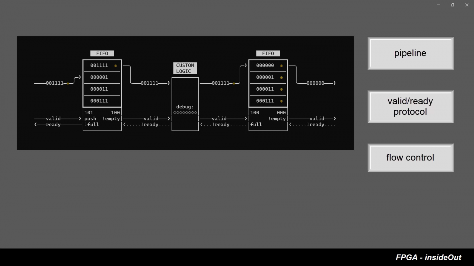
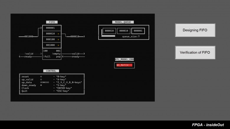
In the last lesson, we explored FIFO buffer using hdlgadgets - human-in-the-loop HDL training tool.
This time we will take two FIFO buffers (which form a pipeline with valid/ready handshakes) and will experiment with it by changing flow-control logic of the pipeline.
We will show that valid/ready is not only a mechanism for transferring data from one FIFO queue to another, but also a method for organizing various kinds of logical functionality between queues.
If you have not worked with valid/ready protocol before, you will be surprised how easy it is to achieve desired functionality of the design by simply writing couple of lines of Verilog code in the handshaking logic block between two FIFOs.
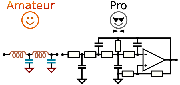

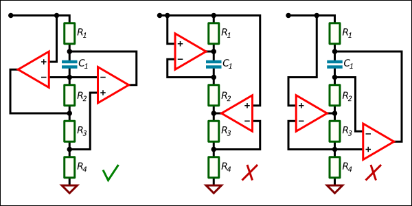
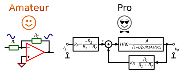
LC ladder component values can have different values for the same transfer function. Published tables have only one set. Why?
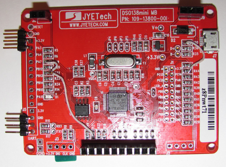
On Ali, an interesting toy – an oscilloscope called DSO138 is sold for a very inexpensive price. It has already gained quite a lot of popularity among electronics lovers, but the parameters of this device, alas, allow it to be more or less fully used only for debugging very low-frequency circuits. Actually, it is not positioned as a tool, but rather as a DIY-kit for novice electronics engineers.
This "toy" oscilloscope is assembled on the STM32F103 microcontroller, and with a fairly competent circuit design of the digital part, the presence of a fairly decent 320X240-dot color display, and not the most rotten analog path, everything, alas, is ruined by very weak ADCs on board the 32F103. The claimed band of 200 kHz can be recognized as such only with a very large stretch. Yes, it will show the presence or absence of a signal with such a frequency, but it will not be possible to really look at something beyond this.
At the same time, the 103-series has a slightly more powerful brother - the STM32F303, it is almost completely compatible with the legs, but it is significantly better in terms of the parameters we are interested in, there are 4 ADCs on board with a conversion frequency of 5 MHz (6 MHz with a 10-bit resolution). In this scenario, if you use all 4 ADCs in parallel with a 10-bit resolution, you can get a effective resolution of up to an honest 24 MSPS (millions of samples per second). The microcontroller is also inexpensive; you can easily find it on the same Ali for very reasonable money again. It is clear that the idea to change the microcontroller arose almost immediately after I tried this DSO138.
At the same time, if upgraded the toy can turn out to be a completely full-fledged tool that even professionals, not just novice amateurs, could already use. With these thoughts in mind, I decided to try to do something with a Chinese toy in my free time.
Ссылка на русскую версию / link to Russian version
FIFO is a key concept in hardware design. Understanding of FIFO is necessary for understanding the valid/ready protocol, which in turn is necessary for organisation of flow-control within a design.
Unfortunately, there are very few books on this topic, and to be fair, microarchitectural concepts are quite difficult to master from books, since understanding of these concepts are coming with practice. In other words it is more about developing hardware intuition.
The idea of the HDL training tool is that it can help develop a hardware intuition, providing the opportunity to explore ready-made scenarios in a step-by-step interactive way. The tool also provides detailed visualization of a simulated scenario.
Since the tool is a front-end for the HDL simulator, the real, synthesized SystemVerilog is executed on the simulator itself, which can be viewed and even modified.
So, the video of exploring FIFO on the training tool is here:
 ChatGPT was not used in writing this article. The animated image uses the webp file format instead of gif. |
In this article, you will find a complete description of how to make a Wi-Fi internet radio receiver from a router that can play mp3 streams from internet radio stations. It is also possible to switch between two internet radio stations. We will use OpenWRT firmware installed on the router to create a Wi-Fi internet radio. It is possible to complete this project without using a soldering iron. All the components can be placed inside the router to create a finished device — a Wi-Fi internet radio. |
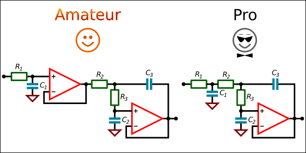
There is a list of well-known electronics design tools for Android which can be found in every review for the last 10 years: “Electrodoc”, “Every Circuit”, “Droid Tesla”, “Electronics Toolbox”, “RF & Microwave Toolbox” and so on. Also, there is a lot of trash on the market that turns finding a good tool into a quest.
This short review is about an unknown but cool tool “Circuit Calculator” working on Android devices and intended for professional electronics designers.
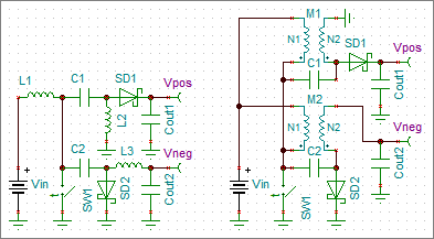
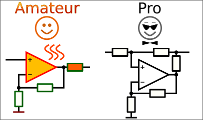
SEPIC-Ćuk split-rail converter can be used to make positive and negative supplies from a single input voltage for relatively well-matched loads like operational amplifiers.
Transient models are time consuming. Average models reduce modeling time drastically.
The PWM switch average models for current- and voltage-mode are described in details in Christophe Basso’s book “Switch-Mode Power Supplies, Second Edition: SPICE Simulations and Practical Designs”. Using of these models for SEPIC and Ćuk converters is also shown.
This text shows how to use the PWM switch average model to design a split-rail SEPIC-Ćuk converter.