SEPIC-Ćuk split-rail converter can be used to make positive and negative supplies from a single input voltage for relatively well-matched loads like operational amplifiers.
Transient models are time consuming. Average models reduce modeling time drastically.
The PWM switch average models for current- and voltage-mode are described in details in Christophe Basso’s book “Switch-Mode Power Supplies, Second Edition: SPICE Simulations and Practical Designs”. Using of these models for SEPIC and Ćuk converters is also shown.
This text shows how to use the PWM switch average model to design a split-rail SEPIC-Ćuk converter.
Circuit
The SEPIC-Ćuk split-rail converter is described in [5] and can be used with uncoupled and coupled inductors.
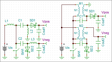
This circuit uses 3 switches, the power switch SW1 and 2 diodes, SD1 and SD2. It creates difficulties in using of the PWM switch average model which is a toggle switch with 2 positions.
Circuit transformation
The transformation steps are shown in the picture below.
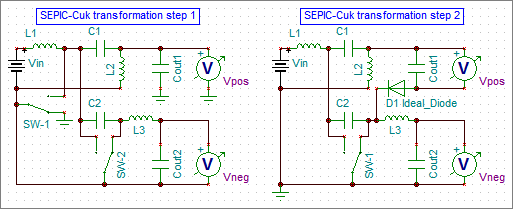
The ideal diode D1 is added to split the current paths and to use only one toggle switch.
Unfortunately, there is no common wire between the output voltages now.
SEPIC-Ćuk split-rail converter with uncoupled inductors
The average model of the converter with 4 V input and +/−12 V 0.5 A outputs is shown in the picture below.
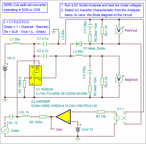
The U2 differential amplifier and the Vref voltage source are used to make the DC operating point. The voltage-to-voltage converter E1 is used to make the connection with the feedback circuit either with the positive or negative output.
TINA-TI does not have a model for the ideal diode, this macro was used:
.subckt d_ideal a k
d1 a k dio
.model dio d is=1e-15 n=1m
.ends d_ideal
A simple transient model was used to verify the average model. The same circuit was run in LTspice with SPICE engine and SIMPLIS with piecewise linear (PWL) modeling.
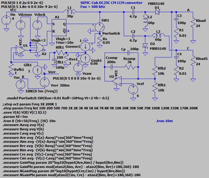
The small-signal control-to-output transfer functions for this SEPIC-Ćuk split-rail converter with uncoupled inductors are shown in the pictures below.
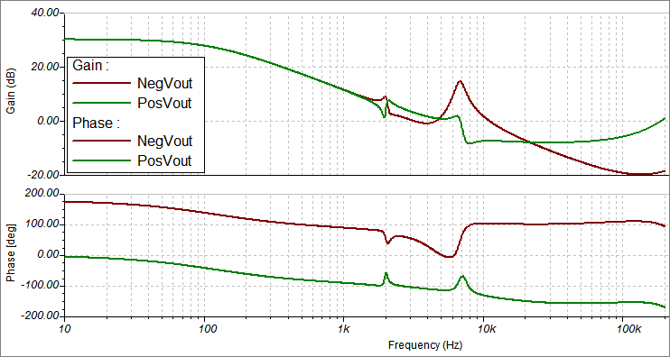
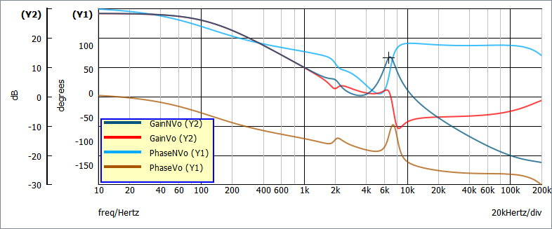
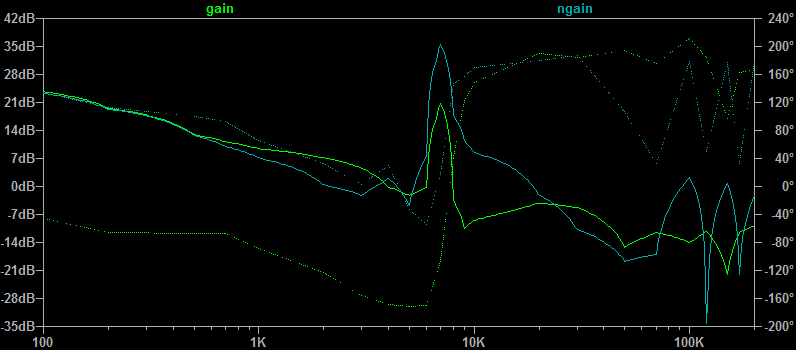
There are the visible differences:
The small “glitch” around 2 kHz is invisible on the transient chart, perhaps, due to the quite large frequency step.
The magnitude of the ringing at 7 kHz is greater at the positive output in the transient model in LTspice than in the average model and SIMPLIS.
There is an abrupt phase change of about 360 degrees above 7 kHz, so the charts look different because of differences in phase unwrapping in the tools.
SEPIC-Ćuk split-rail converter with coupled inductors
The same circuit with coupled inductors is shown in the picture below. The coupling coefficient is set to 0.99.
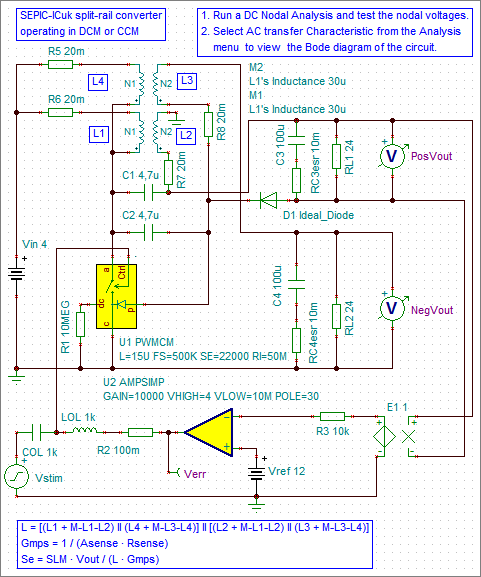
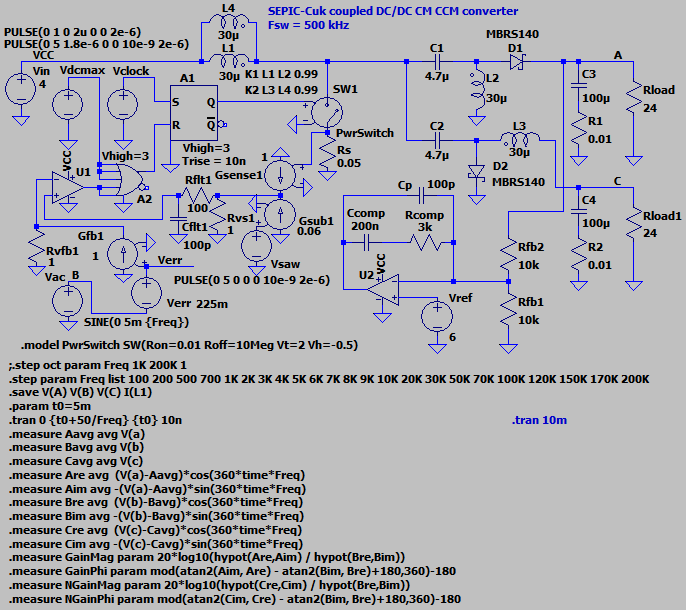
The transient model was modified to verify this circuit as in the circuit below and run in LTspice and SIMPLIS.
The small-signal control-to-output transfer functions for this SEPIC-Ćuk split-rail converter with coupled inductors are shown in the pictures below.
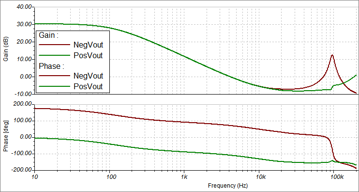
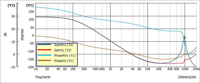
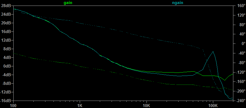
There are not big differences in this case.
Conclusion
A connection of the average PWM switch model is shown to design a SEPIC-Ćuk split-rail converter.
It took couple of hours on my PC to compute 20 points using the transient model, few seconds for 500 points in SIMPLIS and just about 1 second to compute 1000 points using the average model in TINA-TI. And though SIMPLIS is a great tool, it took quite time trying to make the circuits work because of the convergence problem. But the average models just work.
The disadvantage of the shown average model is that there is no common point for the output voltages.
The ringing frequency in the converter with uncoupled inductors is defined by the sum of the inductances and the coupling capacitance, thus it can be quite low. The ringing frequency in the converter with coupled inductors is defined by the sum of the leakage inductances and the coupling capacitance, thus it is much higher than with uncoupled inductors.
As the result, it is better to use the SEPIC-Ćuk split-rail converter with coupled inductors.
The small-signal control-to-output transfer function looks similar to the transfer function of a SEPIC converter, thus a similar design process can be used.
References
Christophe Basso, “Switch-Mode Power Supplies, Second Edition: SPICE Simulations and Practical Designs”, 2nd Edition. Link.
Christophe Basso, personal site. Link.
Christophe Basso, “Transfer Functions of Switching Converters”. Link.
Wei Gu, “A Unified LTspice AC Model for Current-Mode DC-to-DC Converters”. Link.
AD, AN-1106, Kevin Tompsett, “An Improved Topology for Creating Split Rails from a Single Input Voltage”. Link.
TINA-TI, SPICE-based analog simulation program from Texas Instruments. Link.
LTspice. SPICE simulation software from Analog Devices. Link.
SIMetrix/SIMPLIS. Simulation software for the power electronics industry. Link.