Search
Write a publication
Pull to refresh
338.55

Electronics for beginners

Arduino, DYI and how to assemble electronics

Show first
Period
Level of difficulty

The Armenia Opportunity: EDA, ASIC, FPGA + connections with USA, China and Russia

Reading time9 min
Views1.9K

Armenia is a lucky country. Back in the 1990s somebody lobbied Synopsys, the #1 leader in the Electronic Design Automation market, to create a division there. It was joined by Mentor Graphics / Siemens EDA, another EDA leader, then NVidia. Synopsys Armenia became the largest Synopsys division outside the US Silicon Valley and Boston, although the Taiwanese may tell you otherwise. Since Synopsys and Mentor make software used by chip designers in Apple, Samsung, AMD and all other electronic companies, Armenia has an unfair advantage over all their neighbors in Caucasus and Central Asia.

In addition, Armenia has friendly relations with Russia, and most Armenians speak Russian as well. This has facilitated the move of many Russian companies to Armenia, for example, a RISC-V semiconductor IP provider Syntacore. Finally, as we can see from the recent conference EDA Connect, Armenia is attracting the attention of electronic and EDA companies from China.

EDA Connect featured not only academic and industrial papers but also a hackathon on FPGA design, attended by local students from Yerevan State University, the American University of Armenia, the Russian-Armenian University, the French University in Armenia and others.

Read more

The results of 7 Verilog meetups + the goals and the steps going forward

Reading time5 min
Views1.7K

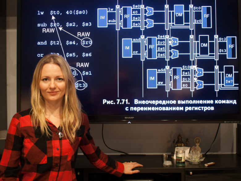
Since the New Year we had 7 Verilog meetups at HackerDojo. We discussed the modern way of designing digital circuits using hardware description languages, the exercises on FPGA boards and the topic of microarchitecture. For the last two sessions we went over the most basic CPU core that can be used as a baseline for further exercises.

Now, in order to make progress toward the goal of creating new educational materials, it is essential for the regular participants to solve all the homework exercises (see the details in the post below) in parallel with studying the recommended materials.

The next steps are:

1) We are going to do weekly Zoom calls on Sundays, starting March 24, 2024 at 11 am California time (summer time). The link. During this call we are going to discuss the SystemVerilog Homework and the individual projects.

2) Once we develop more materials, we are going to organize a Show-and-Tell session in Hacker Dojo, for a wider audience. During the session several participants from the core team will present demos on various FPGA boards and explain to the curious how FPGA and ASIC work.

Read more

A note on small-signal modeling of SEPIC CM CCM

Reading time6 min
Views3.9K

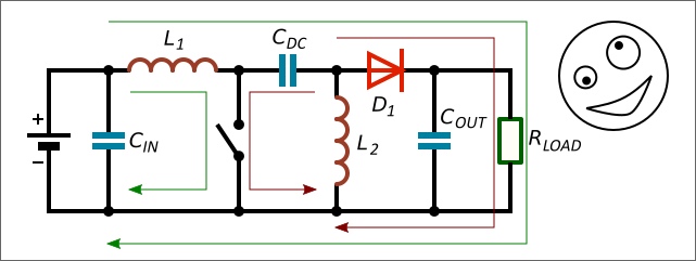
Knowing parameters of small-signal control-to-output transfer functions makes it easier for engineers to design compensation networks of DC/DC converters. The equations for SEPIC can be found in different works and Application Notes, but there are differences. A work has been done to solve this problem.

Simplified design equations for SEPIC with Current Mode control (CM) in Continuous Conduction Mode (CCM) suitable for practical design of compensation networks are shown.

Read more

GoROBO: an educational initiative from the ITMO University startup accelerator

Reading time3 min
Views1.4K
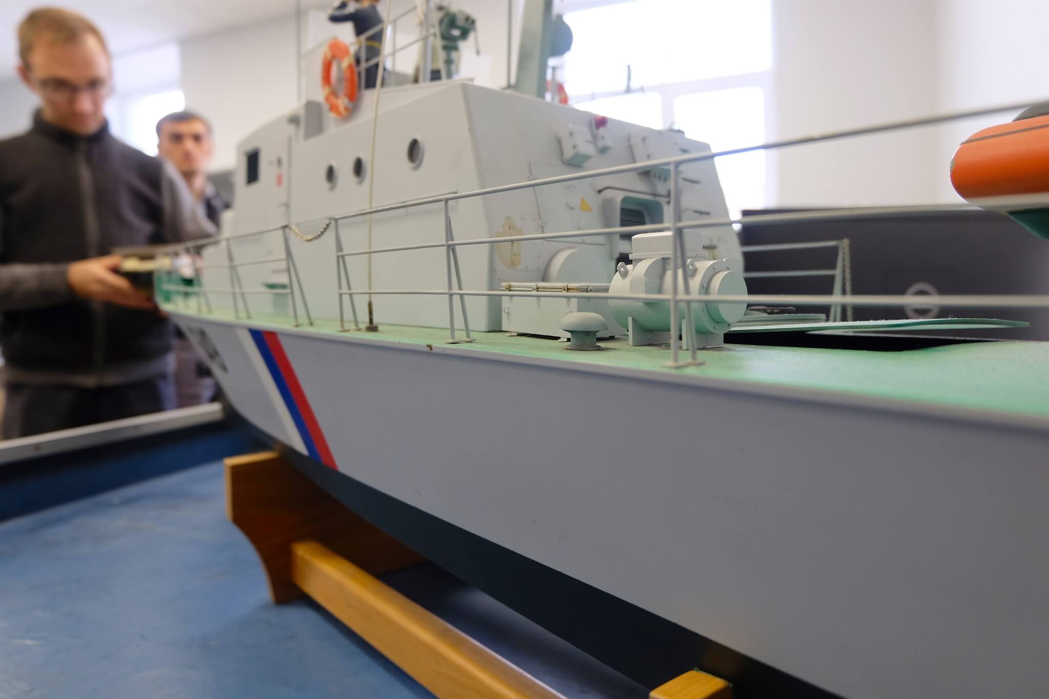
GoROBO is an ITMO University project through and through: one of the co-owners graduated our mechatronics MA program, and two other employees are current postgrad students.

Let’s talk about the educational environment they want to create, why they chose to build such an unusual startup, and what awaits GoROBO clubs in the future.

Read more →

The first Silicon Valley meetup on portable SystemVerilog examples for ASIC and FPGA

Reading time3 min
Views1.1K

Need to start your career or hobby in digital design and verification of silicon chips or reconfigurable hardware? Explore multiple FPGA toolchains and open-source ASIC tools? Design your own RISC-V CPU or ML accelerator? Prepare for an interview in SystemVerilog? Come to our first Silicon Valley meetup on portable SystemVerilog examples for ASIC and FPGA.

Read more

Controlling Brushless Motors using a Linux computer or a PLC

Reading time5 min
Views3K

In this video, we will look at how to connect brushless motor controllers to a Linux computer. Specifically, we will use a computer running Debian. The same steps would work for Ubuntu Linux and other Linux distributions derived from Debian.

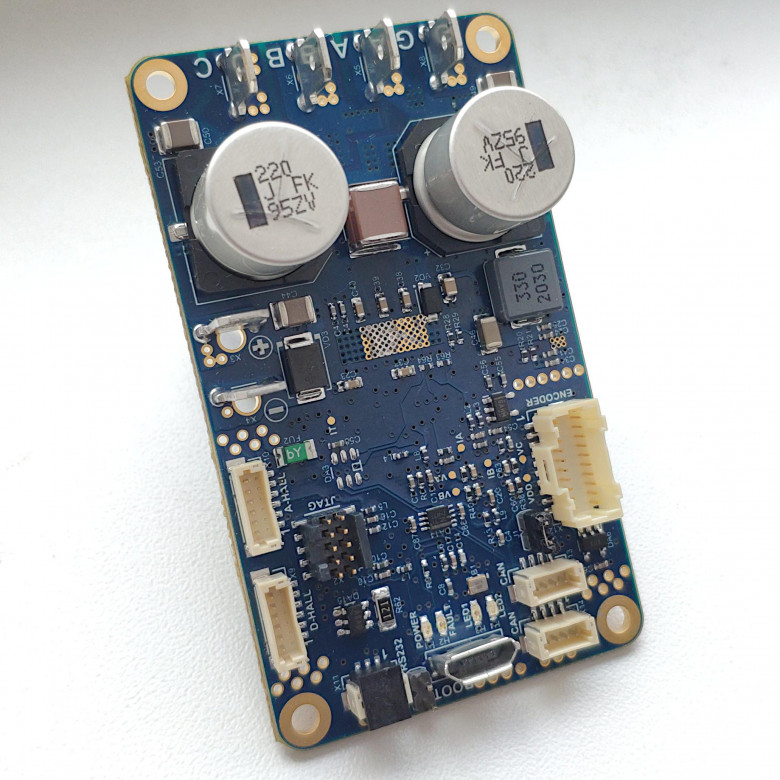
I've got a small sensorless brushless motor, and a bigger brushless motor with a built-in absolute encoder. Lets look at how to control those from my Debian Linux computer. Servosila brushless motor controllers come in several form factors with either a circular or a rectangular shape. The controllers come with a set of connectors for motors and encoders as well as for USB or CANbus networks.

The controllers can be powered by a power supply unit or by a battery. To spice up my setup, I am going to use a battery to power the controllers and thus their motors. The controllers need 7 to 60 volts DC of voltage input. If I connect the battery, the controllers get powered up. The small LED lights tells us that the controllers are happy with the power supply.

We need to connect the brushless motor controllers to the Linux computer. There are two ways to do that - via CANbus or via USB. Lets look at the USB option first. A regular USB cable is used. Only one of the controllers needs to be connected to a computer or a PLC.

Next, we need to build an internal CANbus network between the controllers. We are going to use a CANbus cross-cable to interconnect the controllers. Each controller comes with two identical CANbus ports that help chain multiple controllers together in a network. If one of the interconnected brushless motor controllers is connected to a computer via USB, then that particular controller becomes a USB-to-CANbus gateway for the rest of the network. Up to 16 controllers can be connected this way via a single USB cable to the same control computer or a PLC. The limit is due to finite throughput of the USB interface.

Video & Read more

Making an Encoder Cable for Servosila Brushless Motor Controller. Testing in Direct Drive mode

Reading time2 min
Views983

In this video, we are making a cable for connecting a quadrature encoder to a Servosila brushless motor controller, and and then running a servo motor in Direct Drive mode. To make the cable we are using a cable assembly kit that can be purchased from the internet store. Alternatively, the components for the cable can be bought in other places. The part numbers are given in the controller's datasheet.

The cable assembly kit consists of a connector and a set of wires with pre-crimped socket blades. If you have a crimper tool, you can also attach the socket blades to wires by yourself.

Lets open a datasheet document that comes with the brushless motor controller. Note that each connector has its first pin clearly marked with a "1" sign. Conventionally, the numbering of pins is done in such a way that there are rows of odd-numbered and even-numbered pins.

The quadrature encoder's electrical interface has 5 wires in total. Positions of the pins of each of the wires are given in the table. The socket blades need to be pushed into the connector until you feel a "click". The blades lock into the connector's sockets. Optionally, primarily for cosmetic reasons, you may want to add a heat-shrink tubing to your cable.

The brushless motor controllers come in two distinct forms, a circular and a rectangular one. Both models are identical in terms of capabilities, features, firmware, and external electrical connectors.

The connector has a locking mechanism that keeps it in place. I soldered a mating connector to the other side of the cable - a connector that my brushless motor needs. Note that your motor will likely require a different connector, or no connector at all. It is always a good idea to test an end-to-end integrity of the cable and its connectors. Lets buzz the wires using a multimeter. The cable is ready.

Video & Read more
2

Authors' contribution