
Publish and Play
There exist two main functions of WebRTC operation on the server side in the field of streaming video: publishing and playing. In the case of publishing, the video stream is captured from the web camera and moves from the browser to the server. In the case of playing, the stream moves in the opposite direction, from the server to the browser, is decoded and played in the browser’s HTML5 <video> element on the device’s screen.

UDP and TCP
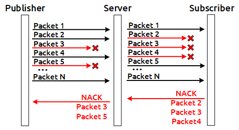
Video can move via two transport protocols: TCP or UDP. In the case of UDP, NACK RTCP feedbacks work actively, carrying the information about the lost packets, due to which it is quite a simple task to detect the UDP channel deterioration, it is boiled down to counting the NACK (Negative ACK) to determine the quality. The more NACK and PLI (Picture Loss Indicator) feedbacks there are, the more real losses there are, and the lower the channel quality is.
TCP without NACK
In this article, we are going to focus more on the TCP protocol. When WebRTC is used over TCP, NACK RTCP feedbacks are not sent, and even if they are sent they do not reflect the real picture of the losses, and it does not seem possible to determine the channel quality by the feedbacks. As it is commonly known, TCP is a transport protocol with guaranteed delivery. For this reason, in case that the channel quality deteriorates the remainder of the packets that there are in the network will be sent on the level of the transport protocol. Sooner or later they will be delivered, but a NACK will not be generated for those losses because in fact there were no losses. As the result, the packets will reach their destination with a delay. The delayed packets simply will not gather into video frames and will be discarded by the depacketizer, as a result of which the user will see a picture like this, full of artifacts:
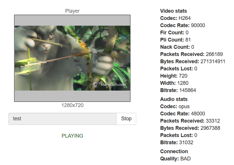
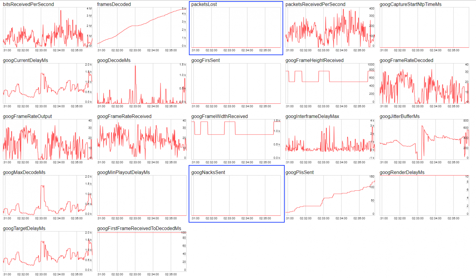
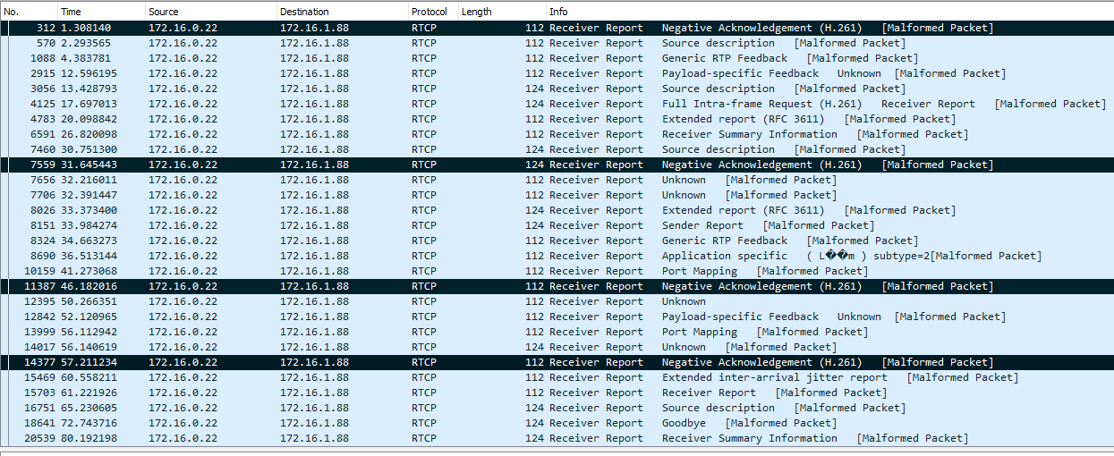
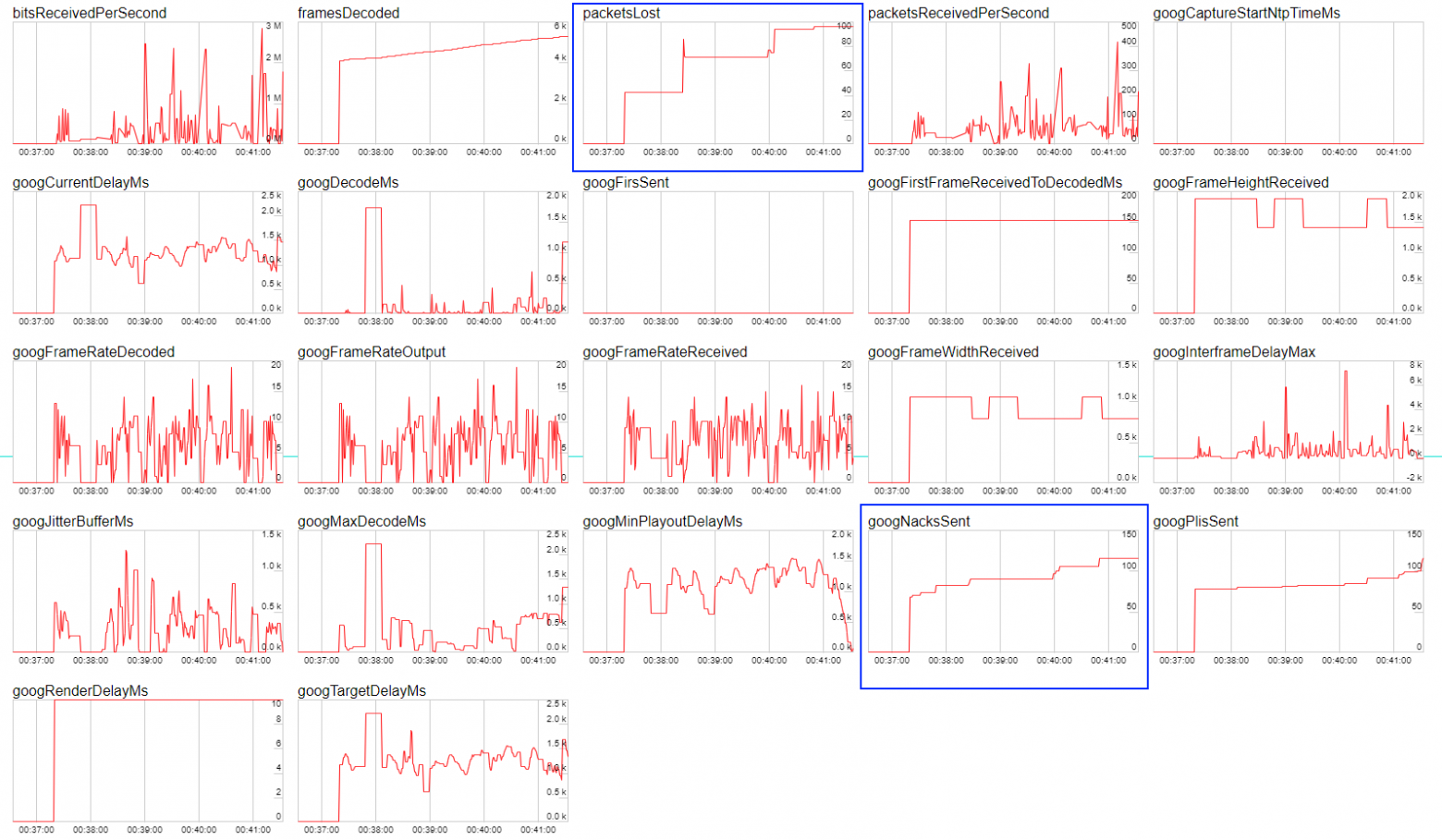
The feedbacks will show that everything is well, but the picture will contain artifacts. Below you can see screenshots of Wireshark traffic which are illustrative of the behavior of the stream being published on compressed TCP and UDP channels, as well as screenshots of Google Chrome statistics. In the screenshots you can see that in the case of TCP, the NACK metric does not grow unlike the UDP, even though the channel’s state is very bad.
TCP
UDP
Why stream over TCP at all if there is UDP
This is a reasonable question to ask. The answer is, for pushing big resolutions through the channel. For example, in the case of VR (Virtual Reality) streaming the resolutions may begin from 4k. It does not seem possible to push a stream with such a resolution and with a bitrate of about 10 Mbps into a regular channel without losses, the server spits out the UDP packets and they begin to be lost in the network in bunches, then the remainder of them begins to be sent, and so on. Big amounts of discarded video packets corrupt the video, and the net result is that the quality becomes very poor. This is the reason why WebRTC over TCP is used for delivering the video in general purpose networks and with high resolutions, such as Full HD and 4k, in order to rule out network packet losses at the expense of a slight increase in the communication latency.
RTT for determining the channel quality
So, there is no metric to tell you for sure that the channel is in a very bad state. Some developers try to rely on the RTT metric but it is far from being able to work in all browsers, and does not give accurate results.
Below you can find an illustration of the dependence of channel quality on RTT according to the callstat project

REMB-based solution
We have decided to take a slightly different approach to this problem. There is the REMB working on the server side, which calculates the incoming bitrate for all incoming streams, calculates its deviation from the mean, and suggests that the browser lowers the bitrate in the case of a significant dispersion, sending specialized REMB commands over the RTCP protocol. The browser receives such a message and lowers the bitrate of the video encoder for the recommended values: this is how the protection against channel overload and incoming stream degradation works. In this way, the bitrate calculation mechanism has already been implemented on the server side. The averaging and determining the dispersion has been are realized via the Kalman filter. This allows for getting the current bitrate at any moment of time with high accuracy and for filtering any significant deviations.
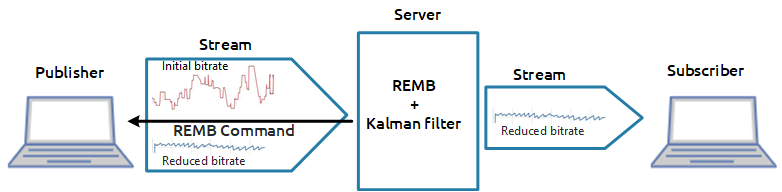
The reader will certainly have this question, “How will it help me to know the bitrate that the server can see for the stream coming into it?” This will only let you understand that there is video coming into the server with a bitrate the value of which it was possible to determine. To evaluate the channel quality, one more component will be required.
The outcoming bitrate, and why it is important
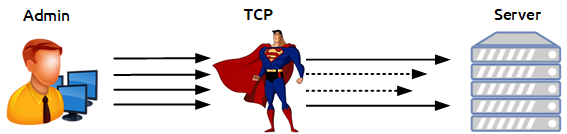
The statistics for the publishing WebRTC stream shows with what bitrate the video stream comes out of the browser. As an old joke goes, a site admin says when checking his assault rifle, “On my side, the bullets have flown out. The problems are on your side...” The idea of checking the channel quality involves comparing two bitrates: 1) the bitrate sent by the browser, 2) the bitrate actually received by the server.
The site admin fires the bullets and calculates the speed they fly out at on his side. The server calculates the speed they are received at on its side. There is one more participant of this event, TCP, this is a superhero who is situated in the middle between the admin and the server and can stop bullets at random. For example, it can stop 10 random bullets of 100 for 2 seconds, and then let them fly again. That’s the Matrix we see here.
On the browser side, we take the current bitrate from the WebRTC statistics, then smooth the graph with the Kalman filter in the JavaScript implementation, and get a smoothed version of the client browser bitrate at the end of the process. Now we have practically all that we need: the client bitrate tells us how the traffic goes out of the browser, and the server bitrate tells us how that traffic is seen by the server, and with what bitrate it is received. It is obvious that if the client bitrate remains high and the server bitrate begins to shrink in relation to the client bitrate, it means that not all of the bullets have “reached the target”, and the server actually cannot see a part of the traffic that was sent to it. On this basis, we can conclude that something is wrong with the channel and it’s time to change the indicator color to red.
And there’s more
The graphs correlate but they are slightly time-shifted in relation to each other. For full correlation it is necessary to time-match the graphs in order to compare the client and server bitrate in the same point of time against historical data. The desynchronization looks approximately like this:
And this is what a time-synchronized graph looks like.
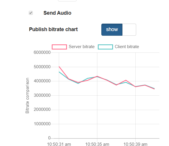
Let’s test it
We have a little left to do, we only have to test it. Let’s publish a video stream, open it, and look at the graph of the published bitrates: on the browser side and on the server side. The graphs demonstrate practically a perfect match. And this is the name of the indicator, PERFECT.

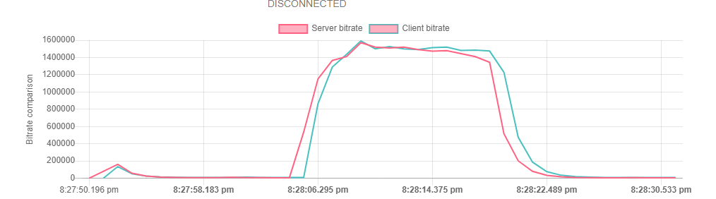
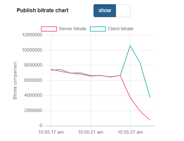
Then, let’s begin to corrupt the channel. To do that, we can use the following free tools: winShaper for Windows or Network Link Conditioner for MacOS. They allow for compressing the channel to the preset value. For example, if we know that a stream of 640x480 can reach a speed of 1 Mbps, let’s compress it to 300 kbs. When doing so we must not forget that we are working with TCP. Let’s check the result of our test: there is inverse correlation in the graphs, and the indicator is slipping to BAD. Indeed, the browser continues to send data and is even increasing the bitrate attempting to push a new portion of traffic into the network. This data accumulates in the network in the form of retransmits and fails to reach the server, as a result the server demonstrates an inverse picture and says that the bitrate it can see has dropped. Indeed, it’s BAD.
We have performed quite many tests that show the correct operation of the indicator. As a result of that we have a feature that makes it possible to reliably and promptly inform the user about any problems with the channel both for stream publishing and playing (working by the same principle). Yeah, all this fuss was for this green and red lamp, PERFECT-BAD. But practice shows that this indicator is very important, and its absence, along with failure to understand the current status, can create big problems for an ordinary user of a WebRTC video streaming service.
Links
WCS 5.2 is a streaming media server for web and mobile application development
Publisher and player channel quality control
REMB — Receiver Estimated Maximum Bitrate used for bandwidth control
NACK — Negative Acknowledgement used for packet lost control and re-transmits
