Let’s find out how to make a simple enough laser projector out of electronics you can find at home.

There are two ways to create an image with a laser — vector scan and raster scan.
During vector scanning, the laser moves along the outlines of the image, only turning off while moving from one outline to the next. That means that the laser is on most of the time, making for a rather bright resulting image.
That method is most often used in large-scale, industrial laser projectors, but it requires the use of a rather complex electro-mechanical device — the galvanometer — to move the laser quickly. Prices start from $80 a pair and it’s very impractical (though possible) to make at home.
The second method is raster scanning. There, the laser beam moves side to side, drawing the image line by line. That’s the method used in old CRT televisions and monitors.
Since both vertical and horizontal movements are done repeatedly, it requires a much simpler mechanical setup than vector scanning. Also, since the image is divided into separate elements, it’s much easier to program.
The main downside of raster scanning is that the beam goes over every element of the image, even those that don’t need to be illuminated, causing the image to be overall dimmer. But, due the simplicity, that’s the method I chose for my laser projector.
To move the laser beam along a line (horizontally), there’s a very convenient technique: is to use a mirror rotating at a constant velocity. Since rotation is continuous, you can move the beam quite fast. But moving the beam to another line is more difficult.
The easiest option is to use multiple lasers pointed at the rotating mirror. The downside is that the number of lines displayed would be determined by the number of lasers used, which makes the setup more complicated, plus you would need quite a high mirror. But there are upsides as well — the only moving part of the whole system is the mirror (less stuff to break), and using multiple lasers can make the image brighter. Here’s an example of a projector built that way.
Another scanning method, often found on the Internet, is combining vertical and horizontal scans by using a spinning mirror drum, where separate “facets” are placed at different angles to the rotating axis. That mirror configuration makes the laser beam reflect into different vertical angles when the mirror is spinning, creating a vertical scan.
Even though the resulting projector is quite simple in essence (you only need a laser, a mirror with a motor and a synchronization sensor), this method has a big downside — it’s very difficult to build a multi-faceted mirror at home. Usually the slant of the “facets” should be adjusted perfectly during construction, and the level of precision required is insanely high.
Here’s an example of such a projector.
To make it easier for myself I used another scanning method — a constantly-rotating mirror to form the horizontal scan and a periodically oscillating mirror for the vertical scan.
Where can you find a fast-rotating mirror? In an old laser printer, of course! Laser printers use a polygonal mirror, set on top of a brushless motor to scan the laser beam along the paper. The motor is usually set on top of the PCB that controls it.
I already had a mirror module from an old printer:

I couldn’t find documentation for the module or the chip inside it, so to determine the module’s pin layout I had to reverse-engineer it. Power lines are easy to locate — they’re connected to the only electrolytic capacitor on the PCB. But simply getting power to the engine isn’t enough to make it spin — you need to also supply a clocking signal to set rotation speed. The signal is a simple meander of the frequency from 20 to 500-1000 Hz.
To find the right line, I grabbed an impulse generator configured for 100 Hz, and connected it (through a resistor) to every available line of the laser module port. Once the signal is supplied to the correct line, the engine starts spinning. Mirror rotates plenty fast for our purposes — as later measured, it spins at a speed over 250 RPS. But unfortunately, the engine’s rotation made it quite noisy. It’s not a problem for my experiments, but would certainly be noticeable when the projector is complete and working. Maybe it could be mitigated by using a newer mirror module or just putting the module in a box.
For preliminary tests I used a laser from a cheap laser pointer. The module should be set up so it has multiple degrees of freedom — to correctly point the laser at the mirror.

Since we use raster scanning, laser light is distributed along the entire area of the image, which makes the image quite dim — it’s only visible in the dark.
So, much later, after I successfully drew an image, I replaced the laser module with a more powerful one — the laser diode from a DVD player.
Both the laser and the polygonal mirror modules were set on top of a small wooden plank. After supplying the clocking signal to the motor and power to the laser, you should point the laser in such a way that the beam hits the edges of the mirror. As a result, while the mirror is rotating, you get a long horizontal line.
To enable the microcontroller to track the position of a moving laser beam, we need a photosensor. But that purpose I used a photodiode obstructed with a piece of cardboard with a small hole in the middle. It’s needed to track the moment the beam hits the photodiode more precise.
Here’s the mounting system for the photodiode (without the cardboard):

During normal operation, the reflected laser beam should first hit the photodiode, and only then — the vertical scan mirror.
After installing the sensor, I tested it by supplying voltage through the resistor and observing the signal with an oscilloscope — its amplitude was enough to connect the sensor directly to the GPIO input of the microcontroller.
As I mentioned earlier, I used a periodically oscillating mirror to form the vertical scan. How do you drive it? The easiest way is to use an electromagnet. Sometimes people just mount the mirrors on top of computer speakers, but it’s not a particularly desirable option (results are inconsistent, too hard to calibrate).
In my build I used the BLDC motor from a DVD player to control the vertical scan mirror. Since the projector was intended for outputting text, there weren't many lines to draw, which meant that the mirror should only be angled slightly.
The BLDC motor consists of three coils, which together make a stator. If one of the coils is connected to a positively-charged power source, and the other two are alternately connected to the negatively-charged source, the engine’s rotor would wobble. The maximum angular sweep is determined by the motor’s configuration, specifically — the number of poles. For a DVD motor it doesn't exceed 30 degrees. Since this motor is quite powerful and easy to control (only two keys are required), this motor fits very well for our purpose of building a text laser projector.
That’s how the motor with a connected mirror looks:

Note that the mirror’s reflective surface should be on the front — meaning, it’s not obstructed by glass.
That’s how the projector looks assembled:

The projection module up close:

The polygonal mirror moves clockwise, so the laser beam moves from left to right.
The powerful DVD laser diode is already installed (inside the collimator). The vertical scan mirror is set up in such a way that the projected image is pointed up — in my case, to the ceiling of my room.
As you can see from the picture, the laser and the projector’s mechanical parts are controlled by the STM32F103 microcontroller installed on a small debugging board (Blue Pill). This board is installed into the breadboard.
Device schematic:
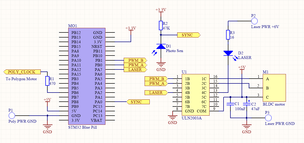
As I mentioned earlier, to control the polygonal mirror motor we need only one signal — the clocking signal (POLY_CLOCK) that’s produced by one of STM32’s timers working in PWM mode. Its frequency and duty ratio are unchanged while the projector is working. To power the motor I use a separate 12V power supply.
The two PWM signals to control the vertical scan mirror are generated by another timer of the microcontroller. These signals are put through a ULN2003A chip that controls the DVD motor. So, by setting different duty ratios for PWM channels of that times, we can change the turning angle of the motor.
Unfortunately, the current version of the projector doesn't provide feedback on mirror location. It means that the microcontroller can drive the mirrors, but it doesn’t «know» it’s current position. The rotor inertia and the coils inductance produce some delays in changing the rotation direction.
Thanks to all this, there are two primary consequences:
Nevertheless, lack of feedback makes the device fairly easy to build.
The process of forming the image is also quite simple:
Laser modulation is done through one of the keys of the ULN2003A chip. The R3 resistor is needed to protect the laser diode from overcurrent. It’s installed right at the end of the laser cable, insulated. To power the laser I used an outboard power supply. It’s important to control the laser current consumption and make sure it’s within the acceptable range for the particular laser diode.
Example of an image (8 lines high):

The text is somewhat out of proportion because the projector points at a wall at an angle. Currently, every vertical scan cycle is 32 steps long (1 step means turning the polygonal mirror by 1 edge).
The projector can display 14 distinct lines: everything after that starts to mix with other lines, corrupting the image.
The photo in the beginning also uses an 8-line font, which makes possible to display even two lines of text somewhat well.
Fonts 11x7 and 6x4 are supported in code too:

Example of “running text”:
The video makes the image flicker vertically, but it’s not visible in reality.
Project on GitHub.
Introduction
There are two ways to create an image with a laser — vector scan and raster scan.
During vector scanning, the laser moves along the outlines of the image, only turning off while moving from one outline to the next. That means that the laser is on most of the time, making for a rather bright resulting image.
That method is most often used in large-scale, industrial laser projectors, but it requires the use of a rather complex electro-mechanical device — the galvanometer — to move the laser quickly. Prices start from $80 a pair and it’s very impractical (though possible) to make at home.
The second method is raster scanning. There, the laser beam moves side to side, drawing the image line by line. That’s the method used in old CRT televisions and monitors.
Since both vertical and horizontal movements are done repeatedly, it requires a much simpler mechanical setup than vector scanning. Also, since the image is divided into separate elements, it’s much easier to program.
The main downside of raster scanning is that the beam goes over every element of the image, even those that don’t need to be illuminated, causing the image to be overall dimmer. But, due the simplicity, that’s the method I chose for my laser projector.
To move the laser beam along a line (horizontally), there’s a very convenient technique: is to use a mirror rotating at a constant velocity. Since rotation is continuous, you can move the beam quite fast. But moving the beam to another line is more difficult.
The easiest option is to use multiple lasers pointed at the rotating mirror. The downside is that the number of lines displayed would be determined by the number of lasers used, which makes the setup more complicated, plus you would need quite a high mirror. But there are upsides as well — the only moving part of the whole system is the mirror (less stuff to break), and using multiple lasers can make the image brighter. Here’s an example of a projector built that way.
Another scanning method, often found on the Internet, is combining vertical and horizontal scans by using a spinning mirror drum, where separate “facets” are placed at different angles to the rotating axis. That mirror configuration makes the laser beam reflect into different vertical angles when the mirror is spinning, creating a vertical scan.
Even though the resulting projector is quite simple in essence (you only need a laser, a mirror with a motor and a synchronization sensor), this method has a big downside — it’s very difficult to build a multi-faceted mirror at home. Usually the slant of the “facets” should be adjusted perfectly during construction, and the level of precision required is insanely high.
Here’s an example of such a projector.
To make it easier for myself I used another scanning method — a constantly-rotating mirror to form the horizontal scan and a periodically oscillating mirror for the vertical scan.
Realization
Horizontal scan
Where can you find a fast-rotating mirror? In an old laser printer, of course! Laser printers use a polygonal mirror, set on top of a brushless motor to scan the laser beam along the paper. The motor is usually set on top of the PCB that controls it.
I already had a mirror module from an old printer:
I couldn’t find documentation for the module or the chip inside it, so to determine the module’s pin layout I had to reverse-engineer it. Power lines are easy to locate — they’re connected to the only electrolytic capacitor on the PCB. But simply getting power to the engine isn’t enough to make it spin — you need to also supply a clocking signal to set rotation speed. The signal is a simple meander of the frequency from 20 to 500-1000 Hz.
To find the right line, I grabbed an impulse generator configured for 100 Hz, and connected it (through a resistor) to every available line of the laser module port. Once the signal is supplied to the correct line, the engine starts spinning. Mirror rotates plenty fast for our purposes — as later measured, it spins at a speed over 250 RPS. But unfortunately, the engine’s rotation made it quite noisy. It’s not a problem for my experiments, but would certainly be noticeable when the projector is complete and working. Maybe it could be mitigated by using a newer mirror module or just putting the module in a box.
Laser
For preliminary tests I used a laser from a cheap laser pointer. The module should be set up so it has multiple degrees of freedom — to correctly point the laser at the mirror.
Since we use raster scanning, laser light is distributed along the entire area of the image, which makes the image quite dim — it’s only visible in the dark.
So, much later, after I successfully drew an image, I replaced the laser module with a more powerful one — the laser diode from a DVD player.
Warning: DVD lasers are very dangerous and can blind you! While working with the laser, use protective glasses at all times!
Both the laser and the polygonal mirror modules were set on top of a small wooden plank. After supplying the clocking signal to the motor and power to the laser, you should point the laser in such a way that the beam hits the edges of the mirror. As a result, while the mirror is rotating, you get a long horizontal line.
Synchronization photosensor
To enable the microcontroller to track the position of a moving laser beam, we need a photosensor. But that purpose I used a photodiode obstructed with a piece of cardboard with a small hole in the middle. It’s needed to track the moment the beam hits the photodiode more precise.
Here’s the mounting system for the photodiode (without the cardboard):
During normal operation, the reflected laser beam should first hit the photodiode, and only then — the vertical scan mirror.
After installing the sensor, I tested it by supplying voltage through the resistor and observing the signal with an oscilloscope — its amplitude was enough to connect the sensor directly to the GPIO input of the microcontroller.
Vertical scan
As I mentioned earlier, I used a periodically oscillating mirror to form the vertical scan. How do you drive it? The easiest way is to use an electromagnet. Sometimes people just mount the mirrors on top of computer speakers, but it’s not a particularly desirable option (results are inconsistent, too hard to calibrate).
In my build I used the BLDC motor from a DVD player to control the vertical scan mirror. Since the projector was intended for outputting text, there weren't many lines to draw, which meant that the mirror should only be angled slightly.
The BLDC motor consists of three coils, which together make a stator. If one of the coils is connected to a positively-charged power source, and the other two are alternately connected to the negatively-charged source, the engine’s rotor would wobble. The maximum angular sweep is determined by the motor’s configuration, specifically — the number of poles. For a DVD motor it doesn't exceed 30 degrees. Since this motor is quite powerful and easy to control (only two keys are required), this motor fits very well for our purpose of building a text laser projector.
That’s how the motor with a connected mirror looks:
Note that the mirror’s reflective surface should be on the front — meaning, it’s not obstructed by glass.
Overview
That’s how the projector looks assembled:

The projection module up close:
The polygonal mirror moves clockwise, so the laser beam moves from left to right.
The powerful DVD laser diode is already installed (inside the collimator). The vertical scan mirror is set up in such a way that the projected image is pointed up — in my case, to the ceiling of my room.
As you can see from the picture, the laser and the projector’s mechanical parts are controlled by the STM32F103 microcontroller installed on a small debugging board (Blue Pill). This board is installed into the breadboard.
Device schematic:
As I mentioned earlier, to control the polygonal mirror motor we need only one signal — the clocking signal (POLY_CLOCK) that’s produced by one of STM32’s timers working in PWM mode. Its frequency and duty ratio are unchanged while the projector is working. To power the motor I use a separate 12V power supply.
The two PWM signals to control the vertical scan mirror are generated by another timer of the microcontroller. These signals are put through a ULN2003A chip that controls the DVD motor. So, by setting different duty ratios for PWM channels of that times, we can change the turning angle of the motor.
Unfortunately, the current version of the projector doesn't provide feedback on mirror location. It means that the microcontroller can drive the mirrors, but it doesn’t «know» it’s current position. The rotor inertia and the coils inductance produce some delays in changing the rotation direction.
Thanks to all this, there are two primary consequences:
- Line density isn’t constant, because the mirror rotation speed can’t be controlled;
- A lot of lines are not operational. The vertical scan mirror vacillates in cycles, so some of the lines could be output downside up, and the other — upside down. A a result, since we can’t track position, lines could only be displayed while the motor is rotating a particular way. Since only half the lines are being displayed, the brightness of the image is halved.
Nevertheless, lack of feedback makes the device fairly easy to build.
The process of forming the image is also quite simple:
- Every time the laser beam hits the photodiode, the microcontroller generates an interrupt. At this interrupt the the current horizontal scan speed is calculated by MCU. After that, the special synchronization timer is reset.
- This synchronization timer generates its own interrupts at particular moments during horizontal scan.
- In particular, some time after synchronization the laser control signal needs to be formed. My device forms it with a DMA+SPI combo. Essentially, these modules transmit a line of the image on the MOSI SPI output at the right time, one bit at a time.
- After the image output is over, the laser should be turned on again,so the photodiode could again accept its beam.
Laser modulation is done through one of the keys of the ULN2003A chip. The R3 resistor is needed to protect the laser diode from overcurrent. It’s installed right at the end of the laser cable, insulated. To power the laser I used an outboard power supply. It’s important to control the laser current consumption and make sure it’s within the acceptable range for the particular laser diode.
Example of an image (8 lines high):
The text is somewhat out of proportion because the projector points at a wall at an angle. Currently, every vertical scan cycle is 32 steps long (1 step means turning the polygonal mirror by 1 edge).
The projector can display 14 distinct lines: everything after that starts to mix with other lines, corrupting the image.
The photo in the beginning also uses an 8-line font, which makes possible to display even two lines of text somewhat well.
Fonts 11x7 and 6x4 are supported in code too:
Example of “running text”:
The video makes the image flicker vertically, but it’s not visible in reality.
Project on GitHub.
