This article is about the interrupt delivery process from external devices in the x86 system. It tries to answer questions such as:
If you want to know the answer for one of these questions, or if you simply want to know about interrupt controller evolution, please, welcome.
For those who don't know what an interrupt is, here is a quote from Wikipedia:
This article is about hardware/external interrupts IRQ.
What is the purpose of interrupts? For example, we want to perform an action with an incoming packet from the network card as soon as the packet arrives. If you don't want to continuously ask the network card «Has my packet arrived?» and waste your processor time, you can use external hardware interrupt IRQ. The interrupt line from a device should be connected to the INTR line of the CPU, and after each packet is received, the network card will make a signal over this line. The CPU will sense this signal and know that the network card has information for it. Only after that the CPU will read the incoming packet.
But what should we do if there are a lot of external devices? It would be very unproductive to make a ton of INTR pins on the CPU for all of them.
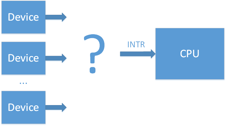
To solve this problem a special chip was invented — an interrupt controller.
(wiki/osdev)
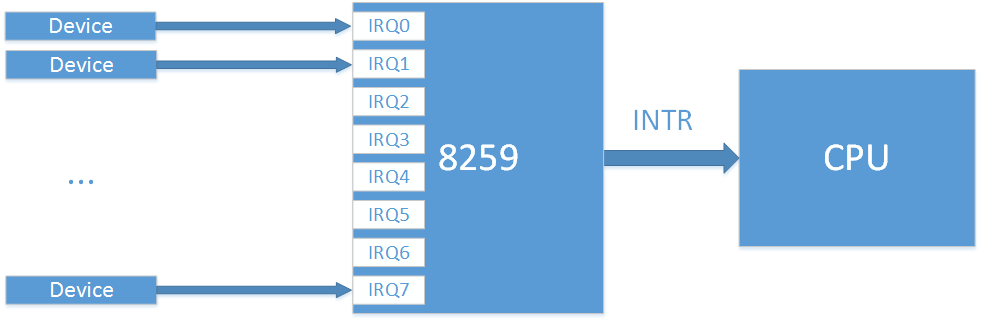
The first interrupt controller chip was the Intel 8259 PIC. It had 8 input lines (IRQ0-7) and 1 output line (which connects the interrupt controller with the INTR line of the CPU). When there is an interrupt from one of the devices on its input lines, the 8259 will make a signal over the INTR line. After that the CPU will know that some device requires its immediate attention, and the processor will ask the PIC which of the 8 input lines (IRQx) was the source of this interrupt. There is some overhead to this polling, but now we have 8 interrupt lines instead of 1.
Soon 8 lines weren't enough. To increase the total number of interrupt lines two 8259 controllers (master and slave) were connected in a cascade (Dual PIC).
IRQs from 0 to 7 are processed with the first Intel 8259 PIC (master), and IRQs from 8 to 15 are processed with the second Intel 8259 PIC (slave). Only the master is connected to the CPU and can signal about the incoming interrupts. If there is an interrupt on lines 8-15, the second PIC (slave) will signal about it to the master on the line IRQ2, and after that the master will signal the CPU. This cascaded interrupt takes away 1 of the 16 lines, but makes a total of 15 interrupts for all external devices.

This scheme was adopted by the community, and now when someone talks about PIC (Programm Interrupt Controller) they mean this Dual PIC system. After some time the 8259 controllers were improved and got a new name: 8259A. With these controllers the DUAL PIC system was included in the chipset. At a time when the main bus for external device connection was the ISA, this system was sufficient. It was only necessary that different devices did not connect to the same IRQ line, since ISA interrupts aren't shareable.
The device interrupt mapping was pretty much standard:
Example (from here):
IRQ 0 — system timer
IRQ 1 — keyboard controller
IRQ 2 — cascade (interrupt from slave controller)
IRQ 3 — serial port COM2
IRQ 4 — serial port COM1
IRQ 5 — parallel port 2 and 3 or sound card
IRQ 6 — floppy controller
IRQ 7 — parallel port 1
IRQ 8 — RTC timer
IRQ 9 — ACPI
IRQ 10 — open/SCSI/NIC
IRQ 11 — open/SCSI/NIC
IRQ 12 — mouse controller
IRQ 13 — math co-processor
IRQ 14 — ATA channel 1
IRQ 15 — ATA channel 2
The configuration and work with 8259 chips is carried out with I/O ports:
Full documentation of the 8259A can be found here.
The PCI bus later replaced the ISA bus. Unfortunately, the number of devices began to exceed the number 15. Also instead of the static ISA bus, devices in the PCI bus can be added to the system dynamically which could potentially lead to even more problems. But luckily, interrupts in the PCI bus can be shared, so it is possible to connect many devices to one interrupt line IRQ. In the end, to solve the problem of lack of interrupt lines, it was decided to group interrupts from all of the PCI devices to PIRQ lines (Programmable Interrupt Request).
For example, suppose we have 4 free interrupt lines on the PIC controller and 20 PCI devices. We can combine interrupts from 5 devices into one PIRQx line, and connect these PIRQx lines to the PIC controller. In this case if there is an interrupt on one of PIRQx lines, the processor will have to ask all the devices connected to this line about the interrupt to know who is responsible for it, but in the end it solves the problem. The device that connects PCI interrupt lines to PIRQ lines is often called a PIR router.
With this method it is necessary to ensure that PIRQx lines don't connect to lines with ISA interrupts (since this will produce conflicts) and that PIRQx lines are balanced (the more devices we connect to one line, the more devices the CPU will need to poll when it needs to check which device is responsible for the interrupt).
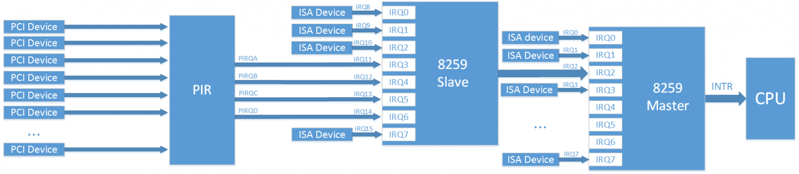
Note: on the image the mapping of PCI device -> PIR is pictured abstractedly, since in the real case it is a little bit more complicated. In the real world each PCI device has 4 interrupt lines (INTA, INTB, INTC, INTD) and up to 8 functions, where each function can have only one of these INTx interrupts. Which INTx line will be used by each function is determined by the chipset configuration.
By their nature functions are separate logical blocks. For example, one PCI device can have an Smbus controller function, a SATA controller function, and an LPC bridge function. From the point of view of an operating system (OS), each function is like a separate device with its own configuration space (PCI config).
Information about a PIC controller interrupt routing is sent to the OS by the BIOS, with the help of the table $PIR and through the registers 3Ch (INT_LN Interrupt Line (R/W)) and 3Dh (INT_PN Interrupt Pin (RO)) of the PCI configuration space for each function.
A specification for the $PIR table was recently on the Microsoft website, but currently is unavailable. It is possible to understand the table's content from PCI BIOS Specification [4.2.2. Get PCI Interrupt Routing Options] or from here (the last link is in Russian, but you can try to google «PCI IRQ Routing Table Specification»)
(wiki, osdev)
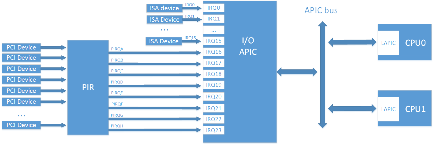
The last method worked until multiprocessor systems arrived. By nature, the PIC can only send interrupts to one CPU, and in a multiprocessor system it is desired to load CPUs in a balanced way. The solution to this problem was the new APIC interface (Advanced PIC).
A special controller called LAPIC (Local APIC) was added for each processor, as well as the I/O APIC controller for routing interrupts from external devices. All of these controllers are combined in a common bus with the name APIC (note that modern systems use a standard system bus instead of a separate APIC bus for this task).
When an external interrupt arrives on the I/O APIC input, the controller will send an interrupt message to the LAPIC of one of the system CPUs. In this way the I/O APIC controller helps balance interrupt load between processors.
The first APIC chip was the 82489DX, which was a separate chip that had a connected LAPIC and I/O APIC within itself. For a dual processor system three such chips were needed: two for LAPIC and one for I/O APIC. Later LAPIC functionality was directly included in processors, and the I/O APIC part was separated to the 82093AA chip.
The I/O APIC 82093AA had 24 inputs, and the APIC architecture could support up to 16 CPUs. Interrupts 0-15 were left for old ISA interrupts for compatibility with older systems, and interrupts 16-23 were meant for all the PCI devices. With this delimitation all conflicts between ISA and PCI interrupts could be easily avoided. With the increased number of free interrupt lines it also became possible to increase the number of PIRQx lines.
I/O APIC and LAPIC programming is done with the help of MMIO. LAPIC registers are usually placed on address 0xFEE00000, and I/O APIC registers on address 0xFEС00000, though it is possible to reconfigure them.
As in the PIC case, separate chips in the beginning became part of the chipset later.
APIC architecture was later modernized, and its new variant was named xAPIC (x — extended). With full backwards compatibility, the total number of possible CPUs in system was increased to 256.
The next step in architecture development was named x2APIC. The number of possible CPUs in the system was increased to 2^32. These controllers can work in a backwards compatibility mode with xAPIC, or they can work in the new x2APIC mode. In this new mode controller programming is not done through MMIO, but through MSR registers (which are much faster). According to this link, IOMMU support is necessary for this mode.
It is worthwhile to note that it is possible to have several I/O APIC controllers in the system. For example, one for 24 interrupts in a southbridge and the other one for 32 interrupts in a northbridge. In the context of I/O APIC, interrupts are usually called GSI (Global System Interrupt). So, the forementioned system has GSIs 0-55.
How can we determine if a CPU has an internal LAPIC and which APIC architecture it supports? It is possible to answer these questions by inspecting bit-flags from CPUID.
To help the OS discover LAPIC and I/O APIC, the BIOS should present information about them either through an MPtable (old method) or through an ACPI table (a MADT table in this case). Besides common information, both the MPtable and the ACPI (in this case a DSDT table) should contain information about the interrupt routing. This means information about which device uses which interrupt line (similar to the $PIR table).
You can read about the MPtable in the official specification. Earlier the specification was on the Intel website, but currently it is only possible to find it in an archive version. The ACPI specification can be found on the UEFI website (current version is 6.2). It is worthwhile to notice that with ACPI it is possible to declare interrupt routing for systems without APIC (instead of providing a separate $PIR table).
(wiki)
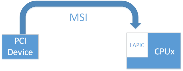
The last variant of APIC was good, but not without downsides. All of the interrupt lines from devices made the system very complicated and thus increased error probability. The PCI express bus came to replace the PCI bus, which simplified all interrupt systems completely. It doesn't have interrupt lines at all. For backwards compatibility interrupt signals (INTx#) are emulated with a separate kind of messages. With PCI interrupt lines their connection was made with physical wires. With PCI express interrupt lines a connection is logical and is made by PCI express bridges. But this support of legacy INTx interrupts only exists for backwards compatibility with the PCI bus. PCI express introduces a completely new method of interrupt delivery — MSI (Message Signaled Interrupts). In this method a device signals about the interrupt simply by writing to a special place in the MMIO region of the CPUs LAPIC.
Earlier a single PCI device (this means all its functions) could have only 4 interrupts, but now it became possible to address up to 32 interrupts.
In the case of MSI there is no sharing of interrupt lines: every interrupt naturally corresponds to its device.
MSI interrupts also solve one more problem. For example, let's imagine a situation where a device makes a memory-write transaction, and wants to signal about its completion through the interrupt. But a write transaction can be delayed on the bus in the process of its transmission (and the device couldn't know about it). In this case the signal about the interrupt will come to the CPU first, so the processor will read not yet valid data. If MSI is used, information about the MSI is transmitted in the same way as data messages, and so it can't come earlier.
It is worthwhile to notice that MSI interrupts can't work without LAPIC, but MSI's can replace I/O APIC (one more design simplification).
After some time the MSI method was extended to MSI-X. Now every device can have up to 2048 interrupts. It is also now possible to specify which CPU should process which interrupt. It can be very useful for highload devices, like network cards for example.
There is no need for a separate BIOS table for MSI support. But the device should indicate its MSI support through one of the Capabilities in its PCI Config space. Also, a device driver should include all necessary support for working with the MSI.
In this article we have studied information about interrupt controller evolution and have got a common theoretical knowledge about interrupt delivery from external devices in the x86 system.
In the next part we will go practice and see how to engage each of forementioned interrupt controllers in Linux.
In the third part we will look into the coreboot code and see what settings are needed in the chipset for correct interrupt routing.
Special thanks to Jacob Garber from the coreboot community for helping me with this article translation.
- What is PIC and what is it for?
- What is APIC and what is it for? What is the purpose of LAPIC and I/O APIC?
- What are the differences between APIC, xAPIC, and x2APIC?
- What is MSI? What are the differences between MSI and MSI-X?
- What is the role of the $PIR, MPtable, and ACPI tables?
If you want to know the answer for one of these questions, or if you simply want to know about interrupt controller evolution, please, welcome.
Introduction
For those who don't know what an interrupt is, here is a quote from Wikipedia:
In system programming, an interrupt is a signal to the processor emitted by hardware or software indicating an event that needs immediate attention. An interrupt alerts the processor to a high-priority condition requiring the interruption of the current code the processor is executing. The processor responds by suspending its current activities, saving its state, and executing a function called an interrupt handler (or an interrupt service routine, ISR) to deal with the event. This interruption is temporary, and, after the interrupt handler finishes, the processor resumes normal activities.
There are two types of interrupts: hardware interrupts and software interrupts (softirqs):
- Hardware interrupts are used by devices to communicate that they require attention from the operating system. Internally, hardware interrupts are implemented using electronic alerting signals that are sent to the processor from an external device, which is either a part of the computer itself, such as a disk controller, or an external peripheral. For example, pressing a key on the keyboard or moving the mouse triggers hardware interrupts that cause the processor to read the keystroke or mouse position. The act of initiating a hardware interrupt is referred to as an interrupt request (IRQ).
- A software interrupt is caused either by an exceptional condition in the processor itself, or a special instruction in the instruction set which causes an interrupt when it is executed. The former is often called a trap or exception and is used for errors or events occurring during program execution that are exceptional enough that they cannot be handled within the program itself. For example, a divide-by-zero exception will be thrown if the processor's arithmetic logic unit is commanded to divide a number by zero as this instruction is an error and impossible.
This article is about hardware/external interrupts IRQ.
What is the purpose of interrupts? For example, we want to perform an action with an incoming packet from the network card as soon as the packet arrives. If you don't want to continuously ask the network card «Has my packet arrived?» and waste your processor time, you can use external hardware interrupt IRQ. The interrupt line from a device should be connected to the INTR line of the CPU, and after each packet is received, the network card will make a signal over this line. The CPU will sense this signal and know that the network card has information for it. Only after that the CPU will read the incoming packet.
But what should we do if there are a lot of external devices? It would be very unproductive to make a ton of INTR pins on the CPU for all of them.
To solve this problem a special chip was invented — an interrupt controller.
PIC
(wiki/osdev)
The first interrupt controller chip was the Intel 8259 PIC. It had 8 input lines (IRQ0-7) and 1 output line (which connects the interrupt controller with the INTR line of the CPU). When there is an interrupt from one of the devices on its input lines, the 8259 will make a signal over the INTR line. After that the CPU will know that some device requires its immediate attention, and the processor will ask the PIC which of the 8 input lines (IRQx) was the source of this interrupt. There is some overhead to this polling, but now we have 8 interrupt lines instead of 1.
Soon 8 lines weren't enough. To increase the total number of interrupt lines two 8259 controllers (master and slave) were connected in a cascade (Dual PIC).
IRQs from 0 to 7 are processed with the first Intel 8259 PIC (master), and IRQs from 8 to 15 are processed with the second Intel 8259 PIC (slave). Only the master is connected to the CPU and can signal about the incoming interrupts. If there is an interrupt on lines 8-15, the second PIC (slave) will signal about it to the master on the line IRQ2, and after that the master will signal the CPU. This cascaded interrupt takes away 1 of the 16 lines, but makes a total of 15 interrupts for all external devices.
This scheme was adopted by the community, and now when someone talks about PIC (Programm Interrupt Controller) they mean this Dual PIC system. After some time the 8259 controllers were improved and got a new name: 8259A. With these controllers the DUAL PIC system was included in the chipset. At a time when the main bus for external device connection was the ISA, this system was sufficient. It was only necessary that different devices did not connect to the same IRQ line, since ISA interrupts aren't shareable.
The device interrupt mapping was pretty much standard:
Example (from here):
IRQ 0 — system timer
IRQ 1 — keyboard controller
IRQ 2 — cascade (interrupt from slave controller)
IRQ 3 — serial port COM2
IRQ 4 — serial port COM1
IRQ 5 — parallel port 2 and 3 or sound card
IRQ 6 — floppy controller
IRQ 7 — parallel port 1
IRQ 8 — RTC timer
IRQ 9 — ACPI
IRQ 10 — open/SCSI/NIC
IRQ 11 — open/SCSI/NIC
IRQ 12 — mouse controller
IRQ 13 — math co-processor
IRQ 14 — ATA channel 1
IRQ 15 — ATA channel 2
The configuration and work with 8259 chips is carried out with I/O ports:
| Chip | Register | I/O port |
|---|---|---|
| Master PIC | Command | 0x0020 |
| Master PIC | Data | 0x0021 |
| Slave PIC | Command | 0x00A0 |
| Slave PIC | Data | 0x00A1 |
Full documentation of the 8259A can be found here.
The PCI bus later replaced the ISA bus. Unfortunately, the number of devices began to exceed the number 15. Also instead of the static ISA bus, devices in the PCI bus can be added to the system dynamically which could potentially lead to even more problems. But luckily, interrupts in the PCI bus can be shared, so it is possible to connect many devices to one interrupt line IRQ. In the end, to solve the problem of lack of interrupt lines, it was decided to group interrupts from all of the PCI devices to PIRQ lines (Programmable Interrupt Request).
For example, suppose we have 4 free interrupt lines on the PIC controller and 20 PCI devices. We can combine interrupts from 5 devices into one PIRQx line, and connect these PIRQx lines to the PIC controller. In this case if there is an interrupt on one of PIRQx lines, the processor will have to ask all the devices connected to this line about the interrupt to know who is responsible for it, but in the end it solves the problem. The device that connects PCI interrupt lines to PIRQ lines is often called a PIR router.
With this method it is necessary to ensure that PIRQx lines don't connect to lines with ISA interrupts (since this will produce conflicts) and that PIRQx lines are balanced (the more devices we connect to one line, the more devices the CPU will need to poll when it needs to check which device is responsible for the interrupt).
Note: on the image the mapping of PCI device -> PIR is pictured abstractedly, since in the real case it is a little bit more complicated. In the real world each PCI device has 4 interrupt lines (INTA, INTB, INTC, INTD) and up to 8 functions, where each function can have only one of these INTx interrupts. Which INTx line will be used by each function is determined by the chipset configuration.
By their nature functions are separate logical blocks. For example, one PCI device can have an Smbus controller function, a SATA controller function, and an LPC bridge function. From the point of view of an operating system (OS), each function is like a separate device with its own configuration space (PCI config).
Information about a PIC controller interrupt routing is sent to the OS by the BIOS, with the help of the table $PIR and through the registers 3Ch (INT_LN Interrupt Line (R/W)) and 3Dh (INT_PN Interrupt Pin (RO)) of the PCI configuration space for each function.
A specification for the $PIR table was recently on the Microsoft website, but currently is unavailable. It is possible to understand the table's content from PCI BIOS Specification [4.2.2. Get PCI Interrupt Routing Options] or from here (the last link is in Russian, but you can try to google «PCI IRQ Routing Table Specification»)
APIC
(wiki, osdev)
The last method worked until multiprocessor systems arrived. By nature, the PIC can only send interrupts to one CPU, and in a multiprocessor system it is desired to load CPUs in a balanced way. The solution to this problem was the new APIC interface (Advanced PIC).
A special controller called LAPIC (Local APIC) was added for each processor, as well as the I/O APIC controller for routing interrupts from external devices. All of these controllers are combined in a common bus with the name APIC (note that modern systems use a standard system bus instead of a separate APIC bus for this task).
When an external interrupt arrives on the I/O APIC input, the controller will send an interrupt message to the LAPIC of one of the system CPUs. In this way the I/O APIC controller helps balance interrupt load between processors.
The first APIC chip was the 82489DX, which was a separate chip that had a connected LAPIC and I/O APIC within itself. For a dual processor system three such chips were needed: two for LAPIC and one for I/O APIC. Later LAPIC functionality was directly included in processors, and the I/O APIC part was separated to the 82093AA chip.
The I/O APIC 82093AA had 24 inputs, and the APIC architecture could support up to 16 CPUs. Interrupts 0-15 were left for old ISA interrupts for compatibility with older systems, and interrupts 16-23 were meant for all the PCI devices. With this delimitation all conflicts between ISA and PCI interrupts could be easily avoided. With the increased number of free interrupt lines it also became possible to increase the number of PIRQx lines.
I/O APIC and LAPIC programming is done with the help of MMIO. LAPIC registers are usually placed on address 0xFEE00000, and I/O APIC registers on address 0xFEС00000, though it is possible to reconfigure them.
As in the PIC case, separate chips in the beginning became part of the chipset later.
APIC architecture was later modernized, and its new variant was named xAPIC (x — extended). With full backwards compatibility, the total number of possible CPUs in system was increased to 256.
The next step in architecture development was named x2APIC. The number of possible CPUs in the system was increased to 2^32. These controllers can work in a backwards compatibility mode with xAPIC, or they can work in the new x2APIC mode. In this new mode controller programming is not done through MMIO, but through MSR registers (which are much faster). According to this link, IOMMU support is necessary for this mode.
It is worthwhile to note that it is possible to have several I/O APIC controllers in the system. For example, one for 24 interrupts in a southbridge and the other one for 32 interrupts in a northbridge. In the context of I/O APIC, interrupts are usually called GSI (Global System Interrupt). So, the forementioned system has GSIs 0-55.
How can we determine if a CPU has an internal LAPIC and which APIC architecture it supports? It is possible to answer these questions by inspecting bit-flags from CPUID.
To help the OS discover LAPIC and I/O APIC, the BIOS should present information about them either through an MPtable (old method) or through an ACPI table (a MADT table in this case). Besides common information, both the MPtable and the ACPI (in this case a DSDT table) should contain information about the interrupt routing. This means information about which device uses which interrupt line (similar to the $PIR table).
You can read about the MPtable in the official specification. Earlier the specification was on the Intel website, but currently it is only possible to find it in an archive version. The ACPI specification can be found on the UEFI website (current version is 6.2). It is worthwhile to notice that with ACPI it is possible to declare interrupt routing for systems without APIC (instead of providing a separate $PIR table).
MSI
(wiki)
The last variant of APIC was good, but not without downsides. All of the interrupt lines from devices made the system very complicated and thus increased error probability. The PCI express bus came to replace the PCI bus, which simplified all interrupt systems completely. It doesn't have interrupt lines at all. For backwards compatibility interrupt signals (INTx#) are emulated with a separate kind of messages. With PCI interrupt lines their connection was made with physical wires. With PCI express interrupt lines a connection is logical and is made by PCI express bridges. But this support of legacy INTx interrupts only exists for backwards compatibility with the PCI bus. PCI express introduces a completely new method of interrupt delivery — MSI (Message Signaled Interrupts). In this method a device signals about the interrupt simply by writing to a special place in the MMIO region of the CPUs LAPIC.
Earlier a single PCI device (this means all its functions) could have only 4 interrupts, but now it became possible to address up to 32 interrupts.
In the case of MSI there is no sharing of interrupt lines: every interrupt naturally corresponds to its device.
MSI interrupts also solve one more problem. For example, let's imagine a situation where a device makes a memory-write transaction, and wants to signal about its completion through the interrupt. But a write transaction can be delayed on the bus in the process of its transmission (and the device couldn't know about it). In this case the signal about the interrupt will come to the CPU first, so the processor will read not yet valid data. If MSI is used, information about the MSI is transmitted in the same way as data messages, and so it can't come earlier.
It is worthwhile to notice that MSI interrupts can't work without LAPIC, but MSI's can replace I/O APIC (one more design simplification).
After some time the MSI method was extended to MSI-X. Now every device can have up to 2048 interrupts. It is also now possible to specify which CPU should process which interrupt. It can be very useful for highload devices, like network cards for example.
There is no need for a separate BIOS table for MSI support. But the device should indicate its MSI support through one of the Capabilities in its PCI Config space. Also, a device driver should include all necessary support for working with the MSI.
Сonclusion
In this article we have studied information about interrupt controller evolution and have got a common theoretical knowledge about interrupt delivery from external devices in the x86 system.
In the next part we will go practice and see how to engage each of forementioned interrupt controllers in Linux.
In the third part we will look into the coreboot code and see what settings are needed in the chipset for correct interrupt routing.
Links:
- Interrupt Controllers (Stuff in the Middle)
- What do the different interrupts in PCIe do?
- Reducing Interrupt Latency Through the Use of Message Signaled Interrupts
Acknowledgments
Special thanks to Jacob Garber from the coreboot community for helping me with this article translation.
