Hey everyone! This is a follow-up article on a local Cisco Russia DevNet Marathon online event I attended in May 2020. It was a series of educational webinars on network automation followed by daily challenges based on the discussed topics.
On a final day, the participants were challenged to automate a topology analysis and visualization of an arbitrary network segment and, optionally, track and visualize the changes.
The task was definitely not trivial and not widely covered in public blog posts. In this article, I would like to break down my own solution that finally took first place and describe the selected toolset and considerations.
Let's get started.

Disclaimer
This is a translation of my original article in Russian I posted in May 2020. If you are willing to help to improve the translation, please DM me.
The article does not aim to cover all the possible scenarios yet does describe the general approaches based on the specific case.
All above and below is an author's personal subjective opinion if not stated otherwise.
All listed code is published under MIT license and does not provide guarantees of any kind.
The solution is written in Python and JavaScript. An understanding of the programming and networking basics is desirable for reading.
If you found a typo, please use Ctrl+Enter or ⌘+Enter to send it to the author.
The Task
The final task description was the following:
There is a network consisting of various L2/L3 network devices running IOS/IOS-XE. You have a list of management IP-addresses of all the devices. All devices are available by their IP addresses. You have access rights to execute any 'show' commands. You are free to use any data gathering methods. But trust us, you unlikely need SNMP. We are not ought to limit your fantasy though.
The primary task is to identify the physical topology and device interconnections based on LLDP data and visualize it in a human-friendly format (yeah, we all find visual diagrams more readable). Then you should save the result in a format suitable for further analysis by the computer (yeah, machines are not that good at reading visual diagrams).
The topology view should include:
- Different icons for each device type (routers and switches may have the same icon).
- Device hostnames.
- Interface names (you may use a shortened format, e.g. Gi0/0 for GigabitEthernet0/0/0).
It is allowed to implement filters limiting or hiding some of the information.
A bonus task is to identify the topology changes (by comparing the current and the previous version) and visualize them in a human-friendly format.
A summary: IP-addresses and credentials as an input, a visualized topology as an output (and a great space for experiments and options somewhere in between).
I also denoted some additional personal considerations to follow while choosing the solution toolset:
- Feature-rich vs Simple balance.
The solution should be balanced in terms of available features and the ease of their usage and implementation. Some ready-to-use open-source free tools might be used. - Familiarity with the selected toolset.
We have had three days to complete the task. The first day I had to spend on some side emergencies. So to be able to provide a working solution within such a limited time frame some known tools were a must. - Solution reusability.
The task is potentially applicable to many production networks. One should keep this in mind. - Support for multiple network platforms.
Real-world networks consist of many platforms. This is a thing to note as well. - The documentation must be available for the chosen toolset.
I believe this is a mandatory requirement for any reusable solution.
Existing solutions
It is always a good idea to check whether the wheel is already invented before reinventing it by yourself. I have made some research on available existing solutions for network visualization. Not surprisingly, no solution could fit all the requirements out of the box. Most such solutions were built into much larger (and typically far not free) enterprise-grade network monitoring and analysis systems which would significantly reduce reusability and customization potential.
Task decomposition and toolset selection
I would divide an abstract network visualization task into the following layers and steps:
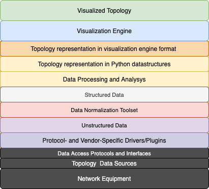
Let's focus on each of them while keeping our requirement in mind:
Network Equipment
The initial task requires us to support IOS and IOS-XE.
Real-world networks tend to be much more heterogeneous. Let's try to consider this.
Topology Data Sources
The task statement suggests us to use LLDP (Link Layer Discovery Protocol) protocol. This is an L2 (OSI Link Layer) protocol described in IEEE 802.1AB standard. It is widely supported by modern network platforms (including IOS and IOS-XE) and operating systems (including Linux and Window), so it suits our case.
The topology data can also be enriched by various outputs from the network devices, such as routing and switching tables, routing protocols data, and so on. Let's just mark it for future improvements.
Data Access Protocols and Standards
The most modern platforms usually support shiny and chrome NETCONF, REST APIs, RESTCONF with YANG models and data structures. The existence of legacy equipment and platforms will usually force us to revert to SSH, Telnet, and good ol' CLI.
Protocol- and Vendor-Specific Drivers or Plugins
The core logic of the solution will be written in Python because of two primary reasons: Python has a pretty comprehensive set of handy modules and libraries for network automation and this is a programming language I am most experienced in.
API-driven network automation in Python can be done using the requests module or some specialized modules.
Bare SSH/Telnet access to network equipment from Python commonly relies on netmiko, paramiko, or scrapli modules. They let you emulate the standard CLI: sending some text commands to the session and expecting back the text output of the more or less predictable readability level and formatting.
There are also several high-level Python frameworks allowing for additional features on top of the tools I mentioned above. The two most useful of them in our case are NAPALM and Nornir. NAPALM provides vendor-neutral GETTERs for getting structured data from the network devices. Nornir implements many useful abstractions and multithreading out of the box.
As for SNMP, let's leave it for network monitoring purposes.
Unstructured Data -> Data Normalization Toolset -> Structured Data
Data gathering with API usually allows you to get structured output straight away. A text output you get from network equipment CLI is natively inapplicable for further machine processing. A traditional way to extract the data from the CLI output in Python is re module and regular expressions. Modern approaches are TextFSM framework developed by Google and brand new TTP (Template Text Parser) developed by dmulyalin. Both tools perform data parsing with more usable templates in comparison to regular expressions.
NAPALM module mentioned above performs unstructured data normalization internally for supported GETTERs and returns the structured output. This may make things some easier in our case.
Data Processing and Analysis -> Topology Representation in Python Datastructures
Once we get the structured topology data pieces from all our devices, all we need to do is to bring it to common representation, analyze and assemble a final puzzle.
Topology Representation in Visualization Engine Format
Depending on visualization engine selection, you may need to transform a final topology data format according to what the tool supports as an input.
Visualization Engine
This point was the most not obvious for me and I had no prior experience in such development. Google search and discussions in DevNet Marathon telegram channel with colleagues introduced me to several Python (pygraphviz, matplotlib, networkx) and JavaScript (JS D3.js, vis.js.) frameworks. Then I found JavaScript+HTML5 NeXt UI Toolkit I once bookmarked while digging through Cisco DevNet labs before. This is a specialized network visualization toolkit developed by Cisco. It has many features and decent documentation.
Visualized Topology
Our final goal. A view may vary from a simple static image or an HTML document to something more advanced and interactive.
Here is a summary of the most common tools we have got:

Based on the requirements above I have selected the following tools for my target solution:
- LLDP is a topology data source.
- SSH and CLI for interaction with the network devices.
- Nornir for multithreading, more useful data gathering result handling and processing, and keeping the information about our devices in a structured Inventory.
- NAPALM to abstract from manual CLI scrapping.
- Python3 for writing the core logic.
- NeXt UI (JS+HTML5) for topology visualization based on result we get from Python peace of code.
I have already used NAPALM and Nornir successfully for network audits and data gathering from hundreds of network devices before. Default NAPALM GETTERs support LLDP on Cisco IOS/IOS-XE, IOS-XR, NX-OS, Juniper JunOS, and Arista EOS.
Furthermore, the logic separation discussed above would allow us to add more data sources and network connectors without affecting the whole codebase.
Next UI was a thing to familiarize with and figure out how it works on the run. However, the examples looked promising.
Preparation
Test lab
I used Cisco Modeling Labs as a test lab. This is a new version of the VIRL network emulator. Cisco DevNet Sandbox allows using it for free for a limited time window. You just have to register and proceed with a reservation which is a matter of a few mouse clicks (and a few more to connect to the lab using AnyConnect VPN once you receive the reservation details back to your email). In the old days we would have to use a production network a bare metal homelab or to have fun with GNS3.
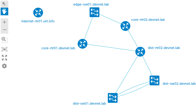
Lab topology on the CML web interface looks as follows (we should get the similar picture as result):

It consists of Cisco devices of any kind: IOS (edge-sw01), IOSXE (internet-rtr01, distr-rtr01, distr-rtr02), NXOS (dist-sw01, dist-sw02), IOSXR (core-rtr01, core-rtr02), ASA (edge-firewall01). LLDP is enabled on all of them. SSH access is available on IOS, IOSXE, and NXOS nodes.
Installing and initializing Nornir
Nornir is an open-source Python framework. It is available on PyPI for Python 3.6.2 and above. Nornir has a dozen of dependencies, including NAPALM and netmiko. It is recommended to use Python virtual environments (venv to isolate the dependencies. My local development environment used Nornir 2.4.0 with Python 3.7 on MacOS 10.15. This should work on Linux and Windows as well. Nornir installation is straightforward:
$ mkdir ~/testenv
$ python3.7 -m venv ~/testenv/
$ source ~/testenv/bin/activate
(testenv)$ pip install nornir==2.4.0
Important: Nornir has had some massive changes in the 3.X release. Some of them were not backward compatible with 2.X versions. Nornir related configurations and code are relevant to 2.X versions.
Nornir supports various inventory plugins. They all provide a convenient way to structure and operate your network devices' information programmatically. For this solution, the standard SimpleInventory plugin is sufficient.
General Nornir settings are listed in a set of YAML files. Configuration file names can be arbitrary but you should point Nornir to their exact names during initialization from Python.
nornir_config.yaml:
---
core:
    num_workers: 20
inventory:
    plugin: nornir.plugins.inventory.simple.SimpleInventory
    options:
        host_file: "inventory/hosts_devnet_sb_cml.yml"
        group_file: "inventory/groups.yml"
A sample Nornir primary configuration file you can see above contains references to two more YAML files: hosts file and groups file. These files define the SimpleInventory plugin configuration. The Hosts file contains a list of our network devices (hosts) with their attributes. Groups file contains a list of groups and their attributes. An individual host can be included in one or more groups. The host inherits the attributes of all groups it belongs to. Hosts and groups file names and locations can be arbitrary as well.
inventory/hosts_devnet_sb_cml.yml has the following structure:
---

internet-rtr01:
    hostname: 10.10.20.181
    platform: ios
    groups:
        - devnet-cml-lab

dist-sw01:
    hostname: 10.10.20.177
    platform: nxos_ssh
    transport: ssh
    groups:
        - devnet-cml-lab
Just two hosts are being displayed for brevity. Both hosts have IP-address, platform attributes. dist-sw01 has transport type assigned specifically. For internet-rtr01, transport type will be chosen based on platform type (it is SSH for IOS by default) by Nornir. Both hosts belong to the 'devnet-cml-lab' group.
groups.yml will define all group settings for them:
---

devnet-cml-lab:
    username: cisco
    password: cisco
    connection_options:
        napalm:
            extras:
                optional_args:
                    secret: cisco
Group attributes above contain access credentials and enable secret for Cisco devices. These attributes will be inherited by all group members.
Important: Never store credentials (and any sensitive data) in your production environment in clear text configs like this. This simple config is used for demonstrational and lab purposes only.
Those are all general Nornir configuration steps. All we need to do now is to initialize it from a Python code.
Downloading NeXt UI
For local usage and testing, it is enough to download the NeXt UI source code from GitHub. Let's put the sources into ./next_sources in our project root directory.
Our progress upon download completion:
$ tree . -L 2
.
├── inventory
│   ├── groups.yml
│   └── hosts_devnet_sb_cml.yml
├── next_sources
│   ├── css
│   ├── doc
│   ├── fonts
│   └── js
├── nornir_config.yml
Age of Topology Discovery
The main logic will be written in a Python script named generate_topology.py.
Initializing Nornir
Once our Nornir config is ready, it can be initialized in Python as simply as:
from nornir import InitNornir
from nornir.plugins.tasks.networking import napalm_get

NORNIR_CONFIG_FILE = "nornir_config.yml"

nr = InitNornir(config_file=NORNIR_CONFIG_FILE)
That's it. Nornir is ready to work.
napalm_get imported above allows us to use NAPALM straight from Nornir.
LLDP at-a-glance
LLDP-enabled devices exchange periodic LLDP messages consisting of TLV-fields with their direct neighbors. LLDP messages are not normally relayed.
Mandatory TLV fields: Chassis ID, Port ID, Time-to-Live.
Optional TLV fields: System Name and Description; Port Name and Description; VLAN Name; IP Management address; System Capabilities (switching, routing, etc.), and more.
As the examined topology segment is under our control, let's consider System Name and Port Name TLV fields required and advertisable internally.
It does not cause significant security risks but allows us to identify multi-chassis devices with a shared control plane (e.g. stacked switches) and device interconnections uniquely.
In this case, a topology analysis task as a whole can be reduced to the analysis of the neighborship data received on each device. This allows us to identify unique devices and their interconnections (i.e. Vertices and Edges of the topology Graph).
By the way, OSPF LSA exchange and analysis work in a very similar way. Visualizing routing protocol data may also be a good use case (I'd recommend to check out the Topolograph service released in October 2020 by @Vadims06). But let's focus on LLDP for now.
In our lab environment, all edge, core, and distribution layer devices should see their direct LLDP neighbors. internet-rtr01 is isolated from the rest of the network so it should not have any LLDP neighbors.
Here is a manual " show lldp neighbors" output from dist-rtr01:
dist-rtr01#show lldp neighbors
Capability codes:
    (R) Router, (B) Bridge, (T) Telephone, (C) DOCSIS Cable Device
    (W) WLAN Access Point, (P) Repeater, (S) Station, (O) Other

Device ID           Local Intf     Hold-time  Capability      Port ID
dist-rtr02.devnet.laGi6            120        R               Gi6
dist-sw01.devnet.labGi4            120        B,R             Ethernet1/3
dist-sw02.devnet.labGi5            120        B,R             Ethernet1/3
core-rtr02.devnet.laGi3            120        R               Gi0/0/0/2
core-rtr01.devnet.laGi2            120        R               Gi0/0/0/2

Total entries displayed: 5
Five neighbors. Looks good.
The same output from core-rtr02:
RP/0/0/CPU0:core-rtr02#show lldp neighbors
Sun May 10 22:07:05.776 UTC
Capability codes:
        (R) Router, (B) Bridge, (T) Telephone, (C) DOCSIS Cable Device
        (W) WLAN Access Point, (P) Repeater, (S) Station, (O) Other

Device ID       Local Intf          Hold-time  Capability     Port ID
core-rtr01.devnet.la Gi0/0/0/0           120        R               Gi0/0/0/0
edge-sw01.devnet.lab Gi0/0/0/1           120        R               Gi0/3
dist-rtr01.devnet.la Gi0/0/0/2           120        R               Gi3
dist-rtr02.devnet.la Gi0/0/0/3           120        R               Gi3

Total entries displayed: 4
Four neighbors. That's correct as well.
Please note that the output contains incomplete hostnames in a Device ID column in both cases.
CLI automation always comes along with such issues.
In our given case the workaround is to use a detailed output format.
As an example:
dist-rtr01#show lldp neighbors detail
------------------------------------------------
Local Intf: Gi6
Chassis id: 001e.e57c.cf00
Port id: Gi6
Port Description: L3 Link to dist-rtr01
System Name: dist-rtr02.devnet.lab

System Description:
Cisco IOS Software [Gibraltar], Virtual XE Software (X86_64_LINUX_IOSD-UNIVERSALK9-M), Version 16.11.1b, RELEASE SOFTWARE (fc2)
Technical Support: http://www.cisco.com/techsupport
Copyright (c) 1986-2019 by Cisco Systems, Inc.
Compiled Tue 28-May-19 12:45

Time remaining: 91 seconds
System Capabilities: B,R
Enabled Capabilities: R
Management Addresses:
    IP: 172.16.252.18
Auto Negotiation - not supported
Physical media capabilities - not advertised
Media Attachment Unit type - not advertised
Vlan ID: - not advertised

------------------------------------------------
Local Intf: Gi4
Chassis id: 5254.0007.5d59
Port id: Ethernet1/3
Port Description: L3 link to dist-rtr01
System Name: dist-sw01.devnet.lab

System Description:
Cisco Nexus Operating System (NX-OS) Software 9.2(3)
TAC support: http://www.cisco.com/tac
Copyright (c) 2002-2019, Cisco Systems, Inc. All rights reserved.

Time remaining: 108 seconds
System Capabilities: B,R
Enabled Capabilities: B,R
Management Addresses:
    IP: 10.10.20.177
    Other: 52 54 00 07 5D 59 00
Auto Negotiation - not supported
Physical media capabilities - not advertised
Media Attachment Unit type - not advertised
Vlan ID: - not advertised

------------------------------------------------
Local Intf: Gi5
Chassis id: 5254.0007.b7e6
Port id: Ethernet1/3
Port Description: L3 link to dist-rtr01
System Name: dist-sw02.devnet.lab

System Description:
Cisco Nexus Operating System (NX-OS) Software 9.2(3)
TAC support: http://www.cisco.com/tac
Copyright (c) 2002-2019, Cisco Systems, Inc. All rights reserved.

Time remaining: 97 seconds
System Capabilities: B,R
Enabled Capabilities: B,R
Management Addresses:
    IP: 10.10.20.178
    Other: 52 54 00 07 FF FF 00
Auto Negotiation - not supported
Physical media capabilities - not advertised
Media Attachment Unit type - not advertised
Vlan ID: - not advertised

------------------------------------------------
Local Intf: Gi3
Chassis id: 02c7.9dc0.0c06
Port id: Gi0/0/0/2
Port Description: L3 Link to dist-rtr01
System Name: core-rtr02.devnet.lab

System Description:
Cisco IOS XR Software, Version 6.3.1[Default]
Copyright (c) 2017 by Cisco Systems, Inc., IOS XRv Series

Time remaining: 94 seconds
System Capabilities: R
Enabled Capabilities: R
Management Addresses:
    IP: 172.16.252.26
Auto Negotiation - not supported
Physical media capabilities - not advertised
Media Attachment Unit type - not advertised
Vlan ID: - not advertised

------------------------------------------------
Local Intf: Gi2
Chassis id: 0288.15c0.0c06
Port id: Gi0/0/0/2
Port Description: L3 Link to dist-rtr01
System Name: core-rtr01.devnet.lab

System Description:
Cisco IOS XR Software, Version 6.3.1[Default]
Copyright (c) 2017 by Cisco Systems, Inc., IOS XRv Series

Time remaining: 110 seconds
System Capabilities: R
Enabled Capabilities: R
Management Addresses:
    IP: 172.16.252.22
Auto Negotiation - not supported
Physical media capabilities - not advertised
Media Attachment Unit type - not advertised
Vlan ID: - not advertised

Total entries displayed: 5
dist-sw01# show lldp neighbors detail
Capability codes:
  (R) Router, (B) Bridge, (T) Telephone, (C) DOCSIS Cable Device
  (W) WLAN Access Point, (P) Repeater, (S) Station, (O) Other
Device ID            Local Intf      Hold-time  Capability  Port ID

Chassis id: 5254.0007.b7e4
Port id: Ethernet1/1
Local Port id: Eth1/1
Port Description: VPC Peer Link
System Name: dist-sw02.devnet.lab
System Description: Cisco Nexus Operating System (NX-OS) Software 9.2(3)
TAC support: http://www.cisco.com/tac
Copyright (c) 2002-2019, Cisco Systems, Inc. All rights reserved.
Time remaining: 112 seconds
System Capabilities: B, R
Enabled Capabilities: B, R
Management Address: 10.10.20.178
Management Address IPV6: not advertised
Vlan ID: 1

Chassis id: 5254.0007.b7e5
Port id: Ethernet1/2
Local Port id: Eth1/2
Port Description: VPC Peer Link
System Name: dist-sw02.devnet.lab
System Description: Cisco Nexus Operating System (NX-OS) Software 9.2(3)
TAC support: http://www.cisco.com/tac
Copyright (c) 2002-2019, Cisco Systems, Inc. All rights reserved.
Time remaining: 112 seconds
System Capabilities: B, R
Enabled Capabilities: B, R
Management Address: 10.10.20.178
Management Address IPV6: not advertised
Vlan ID: 1

Chassis id: 001e.7a2a.3900
Port id: Gi4
Local Port id: Eth1/3
Port Description: L3 Link to dist-sw01
System Name: dist-rtr01.devnet.lab
System Description: Cisco IOS Software [Gibraltar], Virtual XE Software (X86_64_LINUX_IOSD-UNIVERSALK9-M), Version 16.11.1b, RELEASE SOFTWARE (fc2)
Technical Support: http://www.cisco.com/techsupport
Copyright (c) 1986-2019 by Cisco Systems, Inc.
Compiled Tue 28-May-19 12:45
Time remaining: 109 seconds
System Capabilities: B, R
Enabled Capabilities: R
Management Address: 172.16.252.2
Management Address IPV6: not advertised
Vlan ID: not advertised

Chassis id: 001e.e57c.cf00
Port id: Gi4
Local Port id: Eth1/4
Port Description: L3 Link to dist-sw01
System Name: dist-rtr02.devnet.lab
System Description: Cisco IOS Software [Gibraltar], Virtual XE Software (X86_64_LINUX_IOSD-UNIVERSALK9-M), Version 16.11.1b, RELEASE SOFTWARE (fc2)
Technical Support: http://www.cisco.com/techsupport
Copyright (c) 1986-2019 by Cisco Systems, Inc.
Compiled Tue 28-May-19 12:45
Time remaining: 108 seconds
System Capabilities: B, R
Enabled Capabilities: R
Management Address: 172.16.252.6
Management Address IPV6: not advertised
Vlan ID: not advertised

Total entries displayed: 4
Gathering the data from the devices
We are going to gather the LLDP data from the devices running IOS (edge-sw01), IOSXE (internet-rtr01, distr-rtr01, distr-rtr02), and NXOS (dist-sw01, dist-sw02).
IOS-XR-based core routers (core-rtr01, core-rtr02) will be intentionally restricted from management access.
Thereby the following scenarios will be covered:
- Full mesh neighborship handling for all distribution layer devices.
All unique nodes and links should be discovered properly. - Device access or connectivity issues handling for core-rtr01 and core-rtr02.
This should not affect the ability to work with the rest of the devices. - Building the topology based on partial data from discontiguous network segments.
Both edge switch and distribution routers "see" core-rtr01 and core-rtr02 from different sides.
This should be enough to build the full picture.
---

internet-rtr01:
    hostname: 10.10.20.181
    platform: ios
    site: devnet_sandbox
    groups:
        - devnet-cml-lab

edge-sw01:
    hostname: 10.10.20.172
    platform: ios
    site: devnet_sandbox
    groups:
        - devnet-cml-lab

core-rtr01:
    # Device access is restricted for the test
    hostname: 10.10.20.173
    platform: iosxr
    groups:
        - devnet-cml-lab

core-rtr02:
    # Device access is restricted for the test
    hostname: 10.10.20.174
    platform: iosxr
    groups:
        - devnet-cml-lab

dist-rtr01:
    hostname: 10.10.20.175
    platform: ios
    groups:
        - devnet-cml-lab

dist-rtr02:
    hostname: 10.10.20.176
    platform: ios
    groups:
        - devnet-cml-lab

dist-sw01:
    hostname: 10.10.20.177
    platform: nxos_ssh
    transport: ssh
    groups:
        - devnet-cml-lab

dist-sw02:
    hostname: 10.10.20.178
    platform: nxos_ssh
    transport: ssh
    groups:
        - devnet-cml-lab
NAPALM GETTERs to use:
- GET_LLDP_NEIGHBORS_DETAILS.
A detailed output version is chosen as it provides more consistent data. - GET_FACTS.
It collects some extended device information such as FQDN, model, serial number, etc.
Let's wrap the data gathering task into a Nornir Task function.
This is one of useful method of grouping actions on the individual hosts.
def get_host_data(task):
    """Nornir Task for data collection on target hosts."""
    task.run(
        task=napalm_get,
        getters=['facts', 'lldp_neighbors_detail']
    )
Now we can run the Task and save the result into variable for a further processing.
Default execution scope is all devices.
get_host_data_result = nr.run(get_host_data)
You may also use simple and complex inventory filters to limit the execution scope to individual hosts or groups.
Processing the data received from devices
get_host_data_result variable contains a get_host_data task execution results for each target device.
>>> get_host_data_result
AggregatedResult (get_host_data): {'internet-rtr01': MultiResult: [Result: "get_host_data", Result: "napalm_get"], 'edge-sw01': MultiResult: [Result: "get_host_data", Result: "napalm_get"], 'core-rtr01': MultiResult: [Result: "get_host_data", Result: "napalm_get"], 'core-rtr02': MultiResult: [Result: "get_host_data", Result: "napalm_get"], 'dist-rtr01': MultiResult: [Result: "get_host_data", Result: "napalm_get"], 'dist-rtr02': MultiResult: [Result: "get_host_data", Result: "napalm_get"], 'dist-sw01': MultiResult: [Result: "get_host_data", Result: "napalm_get"], 'dist-sw02': MultiResult: [Result: "get_host_data", Result: "napalm_get"]}
Every host result object has failed method returning a boolean value. False means no errors occured during task execution on a specific host.
The global task result is iterable as a dictionalry object:
>>> for device, result in get_host_data_result.items():
...     print(f'{device} failed: {result.failed}')
...
internet-rtr01 failed: False
edge-sw01 failed: False
core-rtr01 failed: True
core-rtr02 failed: True
dist-rtr01 failed: False
dist-rtr02 failed: False
dist-sw01 failed: False
dist-sw02 failed: False
Looks expectedly.
Some complete result outputs for the reference:
>>> get_host_data_result['dist-rtr01'][1].result
{'facts': {'uptime': 6120, 'vendor': 'Cisco', 'os_version': 'Virtual XE Software (X86_64_LINUX_IOSD-UNIVERSALK9-M), Version 16.11.1b, RELEASE SOFTWARE (fc2)', 'serial_number': '9JDCOVUDSWN', 'model': 'CSR1000V', 'hostname': 'dist-rtr01', 'fqdn': 'dist-rtr01.devnet.lab', 'interface_list': ['GigabitEthernet1', 'GigabitEthernet2', 'GigabitEthernet3', 'GigabitEthernet4', 'GigabitEthernet5', 'GigabitEthernet6', 'Loopback0']}, 'lldp_neighbors_detail': {'GigabitEthernet6': [{'remote_chassis_id': '001e.e57c.cf00', 'remote_port': 'Gi6', 'remote_port_description': 'L3 Link to dist-rtr01', 'remote_system_name': 'dist-rtr02.devnet.lab', 'remote_system_description': 'Cisco IOS Software [Gibraltar], Virtual XE Software (X86_64_LINUX_IOSD-UNIVERSALK9-M), Version 16.11.1b, RELEASE SOFTWARE (fc2)', 'remote_system_capab': ['bridge', 'router'], 'remote_system_enable_capab': ['router'], 'parent_interface': ''}], 'GigabitEthernet4': [{'remote_chassis_id': '5254.0007.5d59', 'remote_port': 'Ethernet1/3', 'remote_port_description': 'L3 link to dist-rtr01', 'remote_system_name': 'dist-sw01.devnet.lab', 'remote_system_description': 'Cisco Nexus Operating System (NX-OS) Software 9.2(3)', 'remote_system_capab': ['bridge', 'router'], 'remote_system_enable_capab': ['bridge', 'router'], 'parent_interface': ''}], 'GigabitEthernet5': [{'remote_chassis_id': '5254.0007.b7e6', 'remote_port': 'Ethernet1/3', 'remote_port_description': 'L3 link to dist-rtr01', 'remote_system_name': 'dist-sw02.devnet.lab', 'remote_system_description': 'Cisco Nexus Operating System (NX-OS) Software 9.2(3)', 'remote_system_capab': ['bridge', 'router'], 'remote_system_enable_capab': ['bridge', 'router'], 'parent_interface': ''}], 'GigabitEthernet3': [{'remote_chassis_id': '02c7.9dc0.0c06', 'remote_port': 'Gi0/0/0/2', 'remote_port_description': 'L3 Link to dist-rtr01', 'remote_system_name': 'core-rtr02.devnet.lab', 'remote_system_description': 'Cisco IOS XR Software, Version 6.3.1[Default]', 'remote_system_capab': ['router'], 'remote_system_enable_capab': ['router'], 'parent_interface': ''}], 'GigabitEthernet2': [{'remote_chassis_id': '0288.15c0.0c06', 'remote_port': 'Gi0/0/0/2', 'remote_port_description': 'L3 Link to dist-rtr01', 'remote_system_name': 'core-rtr01.devnet.lab', 'remote_system_description': 'Cisco IOS XR Software, Version 6.3.1[Default]', 'remote_system_capab': ['router'], 'remote_system_enable_capab': ['router'], 'parent_interface': ''}]}}
>>> get_host_data_result['dist-sw01'][1].result
{'facts': {'uptime': 6090, 'vendor': 'Cisco', 'os_version': '9.2(3)', 'serial_number': '9P5OMCCMSQ4', 'model': 'Nexus9000 9000v Chassis', 'hostname': 'dist-sw01', 'fqdn': 'dist-sw01.devnet.lab', 'interface_list': ['mgmt0', 'Ethernet1/1', 'Ethernet1/2', 'Ethernet1/3', 'Ethernet1/4', 'Ethernet1/5', 'Ethernet1/6', 'Ethernet1/7', 'Ethernet1/8', 'Ethernet1/9', 'Ethernet1/10', 'Ethernet1/11', 'Ethernet1/12', 'Ethernet1/13', 'Ethernet1/14', 'Ethernet1/15', 'Ethernet1/16', 'Ethernet1/17', 'Ethernet1/18', 'Ethernet1/19', 'Ethernet1/20', 'Ethernet1/21', 'Ethernet1/22', 'Ethernet1/23', 'Ethernet1/24', 'Ethernet1/25', 'Ethernet1/26', 'Ethernet1/27', 'Ethernet1/28', 'Ethernet1/29', 'Ethernet1/30', 'Ethernet1/31', 'Ethernet1/32', 'Ethernet1/33', 'Ethernet1/34', 'Ethernet1/35', 'Ethernet1/36', 'Ethernet1/37', 'Ethernet1/38', 'Ethernet1/39', 'Ethernet1/40', 'Ethernet1/41', 'Ethernet1/42', 'Ethernet1/43', 'Ethernet1/44', 'Ethernet1/45', 'Ethernet1/46', 'Ethernet1/47', 'Ethernet1/48', 'Ethernet1/49', 'Ethernet1/50', 'Ethernet1/51', 'Ethernet1/52', 'Ethernet1/53', 'Ethernet1/54', 'Ethernet1/55', 'Ethernet1/56', 'Ethernet1/57', 'Ethernet1/58', 'Ethernet1/59', 'Ethernet1/60', 'Ethernet1/61', 'Ethernet1/62', 'Ethernet1/63', 'Ethernet1/64', 'Ethernet1/65', 'Ethernet1/66', 'Ethernet1/67', 'Ethernet1/68', 'Ethernet1/69', 'Ethernet1/70', 'Ethernet1/71', 'Ethernet1/72', 'Ethernet1/73', 'Ethernet1/74', 'Ethernet1/75', 'Ethernet1/76', 'Ethernet1/77', 'Ethernet1/78', 'Ethernet1/79', 'Ethernet1/80', 'Ethernet1/81', 'Ethernet1/82', 'Ethernet1/83', 'Ethernet1/84', 'Ethernet1/85', 'Ethernet1/86', 'Ethernet1/87', 'Ethernet1/88', 'Ethernet1/89', 'Ethernet1/90', 'Ethernet1/91', 'Ethernet1/92', 'Ethernet1/93', 'Ethernet1/94', 'Ethernet1/95', 'Ethernet1/96', 'Ethernet1/97', 'Ethernet1/98', 'Ethernet1/99', 'Ethernet1/100', 'Ethernet1/101', 'Ethernet1/102', 'Ethernet1/103', 'Ethernet1/104', 'Ethernet1/105', 'Ethernet1/106', 'Ethernet1/107', 'Ethernet1/108', 'Ethernet1/109', 'Ethernet1/110', 'Ethernet1/111', 'Ethernet1/112', 'Ethernet1/113', 'Ethernet1/114', 'Ethernet1/115', 'Ethernet1/116', 'Ethernet1/117', 'Ethernet1/118', 'Ethernet1/119', 'Ethernet1/120', 'Ethernet1/121', 'Ethernet1/122', 'Ethernet1/123', 'Ethernet1/124', 'Ethernet1/125', 'Ethernet1/126', 'Ethernet1/127', 'Ethernet1/128', 'Port-channel1', 'Loopback0', 'Vlan1', 'Vlan101', 'Vlan102', 'Vlan103', 'Vlan104', 'Vlan105']}, 'lldp_neighbors_detail': {'Ethernet1/1': [{'remote_chassis_id': '5254.0007.b7e4', 'remote_port': 'Ethernet1/1', 'remote_port_description': 'VPC Peer Link', 'remote_system_name': 'dist-sw02.devnet.lab', 'remote_system_description': 'Cisco Nexus Operating System (NX-OS) Software 9.2(3)', 'remote_system_capab': ['bridge', 'router'], 'remote_system_enable_capab': ['bridge', 'router'], 'parent_interface': ''}], 'Ethernet1/2': [{'remote_chassis_id': '5254.0007.b7e5', 'remote_port': 'Ethernet1/2', 'remote_port_description': 'VPC Peer Link', 'remote_system_name': 'dist-sw02.devnet.lab', 'remote_system_description': 'Cisco Nexus Operating System (NX-OS) Software 9.2(3)', 'remote_system_capab': ['bridge', 'router'], 'remote_system_enable_capab': ['bridge', 'router'], 'parent_interface': ''}], 'Ethernet1/3': [{'remote_chassis_id': '001e.7a2a.3900', 'remote_port': 'Gi4', 'remote_port_description': 'L3 Link to dist-sw01', 'remote_system_name': 'dist-rtr01.devnet.lab', 'remote_system_description': 'Cisco IOS Software [Gibraltar], Virtual XE Software (X86_64_LINUX_IOSD-UNIVERSALK9-M), Version 16.11.1b, RELEASE SOFTWARE (fc2)', 'remote_system_capab': ['bridge', 'router'], 'remote_system_enable_capab': ['router'], 'parent_interface': ''}], 'Ethernet1/4': [{'remote_chassis_id': '001e.e57c.cf00', 'remote_port': 'Gi4', 'remote_port_description': 'L3 Link to dist-sw01', 'remote_system_name': 'dist-rtr02.devnet.lab', 'remote_system_description': 'Cisco IOS Software [Gibraltar], Virtual XE Software (X86_64_LINUX_IOSD-UNIVERSALK9-M), Version 16.11.1b, RELEASE SOFTWARE (fc2)', 'remote_system_capab': ['bridge', 'router'], 'remote_system_enable_capab': ['router'], 'parent_interface': ''}]}}
Result object is a dictionary with a keys matching selected GETTER names: 'facts' and 'lldp_neighbors_detail'.
Dictionary values contain a structured data processed and returned by NAPALM.
Let's compare a neighbor sets:
>>> for neighbor in get_host_data_result['dist-rtr01'][1].result['lldp_neighbors_detail'].items():
...     print(neighbor)
...     print('\n')
...
('GigabitEthernet6', [{'remote_chassis_id': '001e.e57c.cf00', 'remote_port': 'Gi6', 'remote_port_description': 'L3 Link to dist-rtr01', 'remote_system_name': 'dist-rtr02.devnet.lab', 'remote_system_description': 'Cisco IOS Software [Gibraltar], Virtual XE Software (X86_64_LINUX_IOSD-UNIVERSALK9-M), Version 16.11.1b, RELEASE SOFTWARE (fc2)', 'remote_system_capab': ['bridge', 'router'], 'remote_system_enable_capab': ['router'], 'parent_interface': ''}])

('GigabitEthernet4', [{'remote_chassis_id': '5254.0007.5d59', 'remote_port': 'Ethernet1/3', 'remote_port_description': 'L3 link to dist-rtr01', 'remote_system_name': 'dist-sw01.devnet.lab', 'remote_system_description': 'Cisco Nexus Operating System (NX-OS) Software 9.2(3)', 'remote_system_capab': ['bridge', 'router'], 'remote_system_enable_capab': ['bridge', 'router'], 'parent_interface': ''}])

('GigabitEthernet5', [{'remote_chassis_id': '5254.0007.b7e6', 'remote_port': 'Ethernet1/3', 'remote_port_description': 'L3 link to dist-rtr01', 'remote_system_name': 'dist-sw02.devnet.lab', 'remote_system_description': 'Cisco Nexus Operating System (NX-OS) Software 9.2(3)', 'remote_system_capab': ['bridge', 'router'], 'remote_system_enable_capab': ['bridge', 'router'], 'parent_interface': ''}])

('GigabitEthernet3', [{'remote_chassis_id': '02c7.9dc0.0c06', 'remote_port': 'Gi0/0/0/2', 'remote_port_description': 'L3 Link to dist-rtr01', 'remote_system_name': 'core-rtr02.devnet.lab', 'remote_system_description': 'Cisco IOS XR Software, Version 6.3.1[Default]', 'remote_system_capab': ['router'], 'remote_system_enable_capab': ['router'], 'parent_interface': ''}])

('GigabitEthernet2', [{'remote_chassis_id': '0288.15c0.0c06', 'remote_port': 'Gi0/0/0/2', 'remote_port_description': 'L3 Link to dist-rtr01', 'remote_system_name': 'core-rtr01.devnet.lab', 'remote_system_description': 'Cisco IOS XR Software, Version 6.3.1[Default]', 'remote_system_capab': ['router'], 'remote_system_enable_capab': ['router'], 'parent_interface': ''}])
>>> for neighbor in get_host_data_result['dist-sw01'][1].result['lldp_neighbors_detail'].items():
...     print(neighbor)
...     print('\n')
...
('Ethernet1/1', [{'remote_chassis_id': '5254.0007.b7e4', 'remote_port': 'Ethernet1/1', 'remote_port_description': 'VPC Peer Link', 'remote_system_name': 'dist-sw02.devnet.lab', 'remote_system_description': 'Cisco Nexus Operating System (NX-OS) Software 9.2(3)', 'remote_system_capab': ['bridge', 'router'], 'remote_system_enable_capab': ['bridge', 'router'], 'parent_interface': ''}])

('Ethernet1/2', [{'remote_chassis_id': '5254.0007.b7e5', 'remote_port': 'Ethernet1/2', 'remote_port_description': 'VPC Peer Link', 'remote_system_name': 'dist-sw02.devnet.lab', 'remote_system_description': 'Cisco Nexus Operating System (NX-OS) Software 9.2(3)', 'remote_system_capab': ['bridge', 'router'], 'remote_system_enable_capab': ['bridge', 'router'], 'parent_interface': ''}])

('Ethernet1/3', [{'remote_chassis_id': '001e.7a2a.3900', 'remote_port': 'Gi4', 'remote_port_description': 'L3 Link to dist-sw01', 'remote_system_name': 'dist-rtr01.devnet.lab', 'remote_system_description': 'Cisco IOS Software [Gibraltar], Virtual XE Software (X86_64_LINUX_IOSD-UNIVERSALK9-M), Version 16.11.1b, RELEASE SOFTWARE (fc2)', 'remote_system_capab': ['bridge', 'router'], 'remote_system_enable_capab': ['router'], 'parent_interface': ''}])

('Ethernet1/4', [{'remote_chassis_id': '001e.e57c.cf00', 'remote_port': 'Gi4', 'remote_port_description': 'L3 Link to dist-sw01', 'remote_system_name': 'dist-rtr02.devnet.lab', 'remote_system_description': 'Cisco IOS Software [Gibraltar], Virtual XE Software (X86_64_LINUX_IOSD-UNIVERSALK9-M), Version 16.11.1b, RELEASE SOFTWARE (fc2)', 'remote_system_capab': ['bridge', 'router'], 'remote_system_enable_capab': ['router'], 'parent_interface': ''}])
Five neighbors for dist-rtr01 and four neighbors for dist-sw01 which is exactly what we saw in CLI outputs before.
The rest of the data is also valid.
For ease of processing let's split LLDP and facts data into separate entities.
Any devices may be also present in multiple outputs. To distinguish between them, it is necessary to use some unique node identifiers. Let's choose it in the following descending order:
- Device FQDN if available (may be further referred to as hostname for simplicity).
- Device hostname if available.
- Device host object name from Nornir Inventory.
LLDP relies on the first two steps too.
def normalize_result(nornir_job_result):
    """
    get_host_data result parser.
    Returns LLDP and FACTS data dicts
    with hostname keys.
    """
    global_lldp_data = {}
    global_facts = {}
    for device, output in nornir_job_result.items():
        if output[0].failed:
            # Write default data to dicts if the task is failed.
            # Use the host inventory object name as a key.
            global_lldp_data[device] = {}
            global_facts[device] = {
                'nr_ip': nr.inventory.hosts[device].get('hostname', 'n/a'),
            }
            continue
        # Use FQDN as unique ID for devices withing the script.
        device_fqdn = output[1].result['facts']['fqdn']
        if not device_fqdn:
            # If FQDN is not set use hostname.
            # LLDP TLV follows the same logic.
            device_fqdn = output[1].result['facts']['hostname']
        if not device_fqdn:
            # Use host inventory object name as a key if
            # neither FQDN nor hostname are set
            device_fqdn = device
        global_facts[device_fqdn] = output[1].result['facts']
        # Populate device facts with its IP address or hostname as per Inventory data
        global_facts[device_fqdn]['nr_ip'] = nr.inventory.hosts[device].get('hostname', 'n/a')
        global_lldp_data[device_fqdn] = output[1].result['lldp_neighbors_detail']
    return global_lldp_data, global_facts
Then we should extract a list of all neighbors known by devices and build based on that:
- A list of unique hosts.
- A list of unique links between them.
To ensure unambiguous identification of links, we will store them in a following format:
((source_device_id, source_port_name), (destination_device_id, destination_port_name))
It is also necessary to keep in mind that:
- A link may be visible from two sides if we collect the data from both devices it is connected to.
We have to check for side A and side B permutations to filter out the duplicates. - A port name may be formatted differently in the LLDP announcement and local outputs. For example, GigabitEthernet4 locally and Gi4 in LLDP Port name.
To ensure data consistency, we will translate the port names into a full format for the analysis stage. At the same time, let's implement a name shortening function to provide better visual experience during visualization.
Automatic icon selection can be implemented based on device capabilities advertised in LLDP. Let's extract them into a separate {"hostname": "primary_capability"} dictionary.
The same code wise:
interface_full_name_map = {
    'Eth': 'Ethernet',
    'Fa': 'FastEthernet',
    'Gi': 'GigabitEthernet',
    'Te': 'TenGigabitEthernet',
}

def if_fullname(ifname):
    for k, v in interface_full_name_map.items():
        if ifname.startswith(v):
            return ifname
        if ifname.startswith(k):
            return ifname.replace(k, v)
    return ifname

def if_shortname(ifname):
    for k, v in interface_full_name_map.items():
        if ifname.startswith(v):
            return ifname.replace(v, k)
    return ifname

def extract_lldp_details(lldp_data_dict):
    """
    LLDP data dict parser.
    Returns set of all the discovered hosts,
    LLDP capabilities dict with all LLDP-discovered host,
    and all discovered interconnections between hosts.
    """
    discovered_hosts = set()
    lldp_capabilities_dict = {}
    global_interconnections = []
    for host, lldp_data in lldp_data_dict.items():
        if not host:
            continue
        discovered_hosts.add(host)
        if not lldp_data:
            continue
        for interface, neighbors in lldp_data.items():
            for neighbor in neighbors:
                if not neighbor['remote_system_name']:
                    continue
                discovered_hosts.add(neighbor['remote_system_name'])
                if neighbor['remote_system_enable_capab']:
                    # In case of multiple enable capabilities pick first in the list
                    lldp_capabilities_dict[neighbor['remote_system_name']] = (
                        neighbor['remote_system_enable_capab'][0]
                    )
                else:
                    lldp_capabilities_dict[neighbor['remote_system_name']] = ''
                # Store interconnections in a following format:
                # ((source_hostname, source_port), (dest_hostname, dest_port))
                local_end = (host, interface)
                remote_end = (
                    neighbor['remote_system_name'],
                    if_fullname(neighbor['remote_port'])
                )
                # Check if the link is not a permutation of already added one
                # (local_end, remote_end) equals (remote_end, local_end)
                link_is_already_there = (
                    (local_end, remote_end) in global_interconnections
                    or (remote_end, local_end) in global_interconnections
                )
                if link_is_already_there:
                    continue
                global_interconnections.append((
                    (host, interface),
                    (neighbor['remote_system_name'], if_fullname(neighbor['remote_port']))
                ))
    return [discovered_hosts, global_interconnections, lldp_capabilities_dict]
Initializing NeXt UI application
Topology visualization logic will be implemented in next_app.js script based on Next UI.
Let's start with the basics:
(function (nx) {
    /**
     * NeXt UI based application
     */
    // Initialize topology
    var topo = new nx.graphic.Topology({
        // View dimensions
        width: 1200,
        height: 700,
        // Dataprocessor is responsible for spreading
        // the Nodes across the view.
        // 'force' data processor spreads the Nodes so
        // they would be as distant from each other
        // as possible. Follow social distancing and stay healthy.
        // 'quick' dataprocessor picks random positions
        // for the Nodes.
        dataProcessor: 'force',
        // Node and Link identity key attribute name
        identityKey: 'id',
        // Node settings
        nodeConfig: {
            label: 'model.name',
            iconType:'model.icon',
        },
        // Link settings
        linkConfig: {
            // Display Links as curves in case of
            // multiple links between Node Pairs.
            // Set to 'parallel' to use parallel links.
            linkType: 'curve',
        },
        // Display Node icon. Displays a dot if set to 'false'.
        showIcon: true,
    });

    var Shell = nx.define(nx.ui.Application, {
        methods: {
            start: function () {
                // Read topology data from variable
                topo.data(topologyData);
                // Attach it to the document
                topo.attach(this);
            }
        }
    });

    // Create an application instance
    var shell = new Shell();
    // Run the application
    shell.start();
})(nx);
The topology data structure will be stored in a topologyData variable. Let's move it into a separate topology.js file. The format details will be discussed below.
A final visualization result will be displayed in a local HTML form with attached JS components:
<!DOCTYPE html>

<html>
    <head>
        <meta charset="utf-8">
        <link rel="stylesheet" href="next_sources/css/next.css">
        <link rel="stylesheet" href="styles_main_page.css">
        <script src="next_sources/js/next.js"></script>
        <script src="topology.js"></script>
        <script src="next_app.js"></script>
    </head>
    <body>
    </body>
</html>
Generating NeXt UI topology in Python
We have already written required data gathering result handlers and normalized it using Python data structures.
Let's apply this:
GLOBAL_LLDP_DATA, GLOBAL_FACTS = normalize_result(get_host_data_result)
TOPOLOGY_DETAILS = extract_lldp_details(GLOBAL_LLDP_DATA)
General NeXt UI topology representation looks as follows:
// Two nodes connected with two links
var topologyData = {
    "links": [
        {
            "id": 0,
            "source": 0,
            "target": 1,
        }, {
            "id": 1,
            "source": 0,
            "target": 1,
        }
    ],
    "nodes": [
        {
            "icon": "router",
            "id": 0,
        },
        {
            "icon": "router",
            "id": 1,
        }
    ]
As you can see, this is a JSON object which can be mapped to a Python data structure of the following format: {'nodes': [], 'links': []}.
We will bring all our data together into that.
In addition, let's take device model into account for node icon selection to handle missing LLDP capabilities case.
Node objects will also be populated with some extended attributes derived from GET_FACTS (model, S/N, etc) to enrich the topology view.
icon_capability_map = {
    'router': 'router',
    'switch': 'switch',
    'bridge': 'switch',
    'station': 'host'
}

icon_model_map = {
    'CSR1000V': 'router',
    'Nexus': 'switch',
    'IOSXRv': 'router',
    'IOSv': 'switch',
    '2901': 'router',
    '2911': 'router',
    '2921': 'router',
    '2951': 'router',
    '4321': 'router',
    '4331': 'router',
    '4351': 'router',
    '4421': 'router',
    '4431': 'router',
    '4451': 'router',
    '2960': 'switch',
    '3750': 'switch',
    '3850': 'switch',
}

def get_icon_type(device_cap_name, device_model=''):
    """
    Device icon selection function. Selection order:
    - LLDP capabilities mapping.
    - Device model mapping.
    - Default 'unknown'.
    """
    if device_cap_name:
        icon_type = icon_capability_map.get(device_cap_name)
        if icon_type:
            return icon_type
    if device_model:
        # Check substring presence in icon_model_map keys
        # string until the first match
        for model_shortname, icon_type in icon_model_map.items():
            if model_shortname in device_model:
                return icon_type
    return 'unknown'

def generate_topology_json(*args):
    """
    JSON topology object generator.
    Takes as an input:
    - discovered hosts set,
    - LLDP capabilities dict with hostname keys,
    - interconnections list,
    - facts dict with hostname keys.
    """
    discovered_hosts, interconnections, lldp_capabilities_dict, facts = args
    host_id = 0
    host_id_map = {}
    topology_dict = {'nodes': [], 'links': []}
    for host in discovered_hosts:
        device_model = 'n/a'
        device_serial = 'n/a'
        device_ip = 'n/a'
        if facts.get(host):
            device_model = facts[host].get('model', 'n/a')
            device_serial = facts[host].get('serial_number', 'n/a')
            device_ip = facts[host].get('nr_ip', 'n/a')
        host_id_map[host] = host_id
        topology_dict['nodes'].append({
            'id': host_id,
            'name': host,
            'primaryIP': device_ip,
            'model': device_model,
            'serial_number': device_serial,
            'icon': get_icon_type(
                lldp_capabilities_dict.get(host, ''),
                device_model
            )
        })
        host_id += 1
    link_id = 0
    for link in interconnections:
        topology_dict['links'].append({
            'id': link_id,
            'source': host_id_map[link[0][0]],
            'target': host_id_map[link[1][0]],
            'srcIfName': if_shortname(link[0][1]),
            'srcDevice': link[0][0],
            'tgtIfName': if_shortname(link[1][1]),
            'tgtDevice': link[1][0],
        })
        link_id += 1
    return topology_dict
Then we should just write this Python topology dictionary into the topology.js file. A standard json module will work for this perfectly providing a readable and formatted output:
import json

OUTPUT_TOPOLOGY_FILENAME = 'topology.js'
TOPOLOGY_FILE_HEAD = "\n\nvar topologyData = "

def write_topology_file(topology_json, header=TOPOLOGY_FILE_HEAD, dst=OUTPUT_TOPOLOGY_FILENAME):
    with open(dst, 'w') as topology_file:
        topology_file.write(header)
        topology_file.write(json.dumps(topology_json, indent=4, sort_keys=True))
        topology_file.write(';')

TOPOLOGY_DICT = generate_topology_json(*TOPOLOGY_DETAILS)
write_topology_file(TOPOLOGY_DICT)
var topologyData = {
    "links": [
        {
            "id": 0,
            "source": 7,
            "srcDevice": "edge-sw01.devnet.lab",
            "srcIfName": "Gi0/2",
            "target": 5,
            "tgtDevice": "core-rtr01.devnet.lab",
            "tgtIfName": "Gi0/0/0/1"
        },
        {
            "id": 1,
            "source": 7,
            "srcDevice": "edge-sw01.devnet.lab",
            "srcIfName": "Gi0/3",
            "target": 3,
            "tgtDevice": "core-rtr02.devnet.lab",
            "tgtIfName": "Gi0/0/0/1"
        },
        {
            "id": 2,
            "source": 4,
            "srcDevice": "dist-rtr01.devnet.lab",
            "srcIfName": "Gi3",
            "target": 3,
            "tgtDevice": "core-rtr02.devnet.lab",
            "tgtIfName": "Gi0/0/0/2"
        },
        {
            "id": 3,
            "source": 4,
            "srcDevice": "dist-rtr01.devnet.lab",
            "srcIfName": "Gi4",
            "target": 1,
            "tgtDevice": "dist-sw01.devnet.lab",
            "tgtIfName": "Eth1/3"
        },
        {
            "id": 4,
            "source": 4,
            "srcDevice": "dist-rtr01.devnet.lab",
            "srcIfName": "Gi6",
            "target": 0,
            "tgtDevice": "dist-rtr02.devnet.lab",
            "tgtIfName": "Gi6"
        },
        {
            "id": 5,
            "source": 4,
            "srcDevice": "dist-rtr01.devnet.lab",
            "srcIfName": "Gi5",
            "target": 2,
            "tgtDevice": "dist-sw02.devnet.lab",
            "tgtIfName": "Eth1/3"
        },
        {
            "id": 6,
            "source": 4,
            "srcDevice": "dist-rtr01.devnet.lab",
            "srcIfName": "Gi2",
            "target": 5,
            "tgtDevice": "core-rtr01.devnet.lab",
            "tgtIfName": "Gi0/0/0/2"
        },
        {
            "id": 7,
            "source": 0,
            "srcDevice": "dist-rtr02.devnet.lab",
            "srcIfName": "Gi3",
            "target": 3,
            "tgtDevice": "core-rtr02.devnet.lab",
            "tgtIfName": "Gi0/0/0/3"
        },
        {
            "id": 8,
            "source": 0,
            "srcDevice": "dist-rtr02.devnet.lab",
            "srcIfName": "Gi4",
            "target": 1,
            "tgtDevice": "dist-sw01.devnet.lab",
            "tgtIfName": "Eth1/4"
        },
        {
            "id": 9,
            "source": 0,
            "srcDevice": "dist-rtr02.devnet.lab",
            "srcIfName": "Gi5",
            "target": 2,
            "tgtDevice": "dist-sw02.devnet.lab",
            "tgtIfName": "Eth1/4"
        },
        {
            "id": 10,
            "source": 0,
            "srcDevice": "dist-rtr02.devnet.lab",
            "srcIfName": "Gi2",
            "target": 5,
            "tgtDevice": "core-rtr01.devnet.lab",
            "tgtIfName": "Gi0/0/0/3"
        },
        {
            "id": 11,
            "source": 1,
            "srcDevice": "dist-sw01.devnet.lab",
            "srcIfName": "Eth1/1",
            "target": 2,
            "tgtDevice": "dist-sw02.devnet.lab",
            "tgtIfName": "Eth1/1"
        },
        {
            "id": 12,
            "source": 1,
            "srcDevice": "dist-sw01.devnet.lab",
            "srcIfName": "Eth1/2",
            "target": 2,
            "tgtDevice": "dist-sw02.devnet.lab",
            "tgtIfName": "Eth1/2"
        }
    ],
    "nodes": [
        {
            "icon": "router",
            "id": 0,
            "model": "CSR1000V",
            "name": "dist-rtr02.devnet.lab",
            "serial_number": "9YZKNQKQ566",
            "layerSortPreference": 7,
            "primaryIP": "10.10.20.176",
            "dcimDeviceLink": "http://localhost:32768/dcim/devices/?q=dist-rtr02.devnet.lab"
        },
        {
            "icon": "switch",
            "id": 1,
            "model": "Nexus9000 9000v Chassis",
            "name": "dist-sw01.devnet.lab",
            "serial_number": "9MZLNM0ZC9Z",
        },
        {
            "icon": "switch",
            "id": 2,
            "model": "Nexus9000 9000v Chassis",
            "name": "dist-sw02.devnet.lab",
            "serial_number": "93LCGCRUJA5",
        },
        {
            "icon": "router",
            "id": 3,
            "model": "n/a",
            "name": "core-rtr02.devnet.lab",
            "serial_number": "n/a",
        },
        {
            "icon": "router",
            "id": 4,
            "model": "CSR1000V",
            "name": "dist-rtr01.devnet.lab",
            "serial_number": "9S78ZRF2V2B",
        },
        {
            "icon": "router",
            "id": 5,
            "model": "n/a",
            "name": "core-rtr01.devnet.lab",
            "serial_number": "n/a",
        },
        {
            "icon": "router",
            "id": 6,
            "model": "CSR1000V",
            "name": "internet-rtr01.virl.info",
            "serial_number": "9LGWPM8GTV6",
        },
        {
            "icon": "switch",
            "id": 7,
            "model": "IOSv",
            "name": "edge-sw01.devnet.lab",
            "serial_number": "927A4RELIGI",
        }
    ]
};
Now let's finally run main.html and see our visualization Hello World:

Looks correct. All known nodes and links between them are displayed.
The nodes are draggable in any direction. On mouse click on nodes and links, a Next UI tooltip menu appears. It contains all the attributes we previously passed into node and link topology objects in Python:

Not so bad. There is also room for improvement. We will return to this some later on. Let's implement a solution for the second part of the task for now.
Detecting and visualizing topology changes
A bonus task is to detect and visualize topology changes.
To get it done, some additions will be required:
- A topology cache file cached_topology.js to store a previous topology state.
generate_topology.py script will be reading this cache file on each run and rewriting with a newer state if necessary. - diff_topology.js topology file to store a diff topology.
- diff_page.html page to display a visualized topology diff.
Diff HTML-form will look as follows:
<!DOCTYPE html>

<html>
    <head>
        <meta charset="utf-8">
        <link rel="stylesheet" href="next_sources/css/next.css">
        <link rel="stylesheet" href="styles_main_page.css">
        <script src="next_sources/js/next.js"></script>
        <script src="diff_topology.js"></script>
        <script src="next_app.js"></script>
    </head>
    <body>
        <a href="main.html"><button>Display current topology</button></a>
        </p>
    </body>
</html>
All we need to read and write topology cache files:
CACHED_TOPOLOGY_FILENAME = 'cached_topology.json'

def write_topology_cache(topology_json, dst=CACHED_TOPOLOGY_FILENAME):
    with open(dst, 'w') as cached_file:
        cached_file.write(json.dumps(topology_json, indent=4, sort_keys=True))

def read_cached_topology(filename=CACHED_TOPOLOGY_FILENAME):
    if not os.path.exists(filename):
        return {}
    if not os.path.isfile(filename):
        return {}
    cached_topology = {}
    with open(filename, 'r') as file:
        try:
            cached_topology = json.loads(file.read())
        except:
            return {}
    return cached_topology
Topology diff analysis steps:
Extract the node and link attributes for comparison from the current and cached topology dictionaries.
Node format:
(node object with all attributes, (hostname,))
Link format:
(link object with all attributes, (source_hostnme, source_port), (dest_hostname, dest_port))
Both node and link format allows further extension.
Compare the extracted node and link objects. Link format permutations should be considered.
Diff result for nodes and links will be written into two dictionaries in the following format:
- diff_nodes = {'added': [], 'deleted': []}
- diff_links = {'added': [], 'deleted': []}
Merge current and cached topology with the diff data.
The resulting topology will be written to diff_merged_topology dictionary.
Deleted node and link objects will be extended with the is_dead attribute. For a better visual experience, deleted node icons will be customized (Next UI changes for that will be discussed below).
New node and link objects will be extended with the is_new attribute.
Let's code:
def get_topology_diff(cached, current):
    """
    Topology diff analyzer and generator.
    Accepts two valid topology dicts as an input.
    Returns:
    - dict with added and deleted nodes,
    - dict with added and deleted links,
    - dict with merged input topologies with extended
      attributes for topology changes visualization
    """
    diff_nodes = {'added': [], 'deleted': []}
    diff_links = {'added': [], 'deleted': []}
    diff_merged_topology = {'nodes': [], 'links': []}
    # Parse links from topology dicts into the following format:
    # (topology_link_obj, (source_hostnme, source_port), (dest_hostname, dest_port))
    cached_links = [(x, ((x['srcDevice'], x['srcIfName']), (x['tgtDevice'], x['tgtIfName']))) for x in cached['links']]
    links = [(x, ((x['srcDevice'], x['srcIfName']), (x['tgtDevice'], x['tgtIfName']))) for x in current['links']]
    # Parse nodes from topology dicts into the following format:
    # (topology_node_obj, (hostname,))
    # Some additional values might be added for comparison later on to the tuple above.
    cached_nodes = [(x, (x['name'],)) for x in cached['nodes']]
    nodes = [(x, (x['name'],)) for x in current['nodes']]
    # Search for deleted and added hostnames.
    node_id = 0
    host_id_map = {}
    for raw_data, node in nodes:
        if node in [x[1] for x in cached_nodes]:
            raw_data['id'] = node_id
            host_id_map[raw_data['name']] = node_id
            raw_data['is_new'] = 'no'
            raw_data['is_dead'] = 'no'
            diff_merged_topology['nodes'].append(raw_data)
            node_id += 1
            continue
        diff_nodes['added'].append(node)
        raw_data['id'] = node_id
        host_id_map[raw_data['name']] = node_id
        raw_data['is_new'] = 'yes'
        raw_data['is_dead'] = 'no'
        diff_merged_topology['nodes'].append(raw_data)
        node_id += 1
    for raw_data, cached_node in cached_nodes:
        if cached_node in [x[1] for x in nodes]:
            continue
        diff_nodes['deleted'].append(cached_node)
        raw_data['id'] = node_id
        host_id_map[raw_data['name']] = node_id
        raw_data['is_new'] = 'no'
        raw_data['is_dead'] = 'yes'
        raw_data['icon'] = 'dead_node'
        diff_merged_topology['nodes'].append(raw_data)
        node_id += 1
    # Search for deleted and added interconnections.
    # Interface change on some side is considered as
    # one interconnection deletion and one interconnection insertion.
    # Check for permutations as well:
    # ((h1, Gi1), (h2, Gi2)) and ((h2, Gi2), (h1, Gi1)) are equal.
    link_id = 0
    for raw_data, link in links:
        src, dst = link
        if not (src, dst) in [x[1] for x in cached_links] and not (dst, src) in [x[1] for x in cached_links]:
            diff_links['added'].append((src, dst))
            raw_data['id'] = link_id
            link_id += 1
            raw_data['source'] = host_id_map[src[0]]
            raw_data['target'] = host_id_map[dst[0]]
            raw_data['is_new'] = 'yes'
            raw_data['is_dead'] = 'no'
            diff_merged_topology['links'].append(raw_data)
            continue
        raw_data['id'] = link_id
        link_id += 1
        raw_data['source'] = host_id_map[src[0]]
        raw_data['target'] = host_id_map[dst[0]]
        raw_data['is_new'] = 'no'
        raw_data['is_dead'] = 'no'
        diff_merged_topology['links'].append(raw_data)
    for raw_data, link in cached_links:
        src, dst = link
        if not (src, dst) in [x[1] for x in links] and not (dst, src) in [x[1] for x in links]:
            diff_links['deleted'].append((src, dst))
            raw_data['id'] = link_id
            link_id += 1
            raw_data['source'] = host_id_map[src[0]]
            raw_data['target'] = host_id_map[dst[0]]
            raw_data['is_new'] = 'no'
            raw_data['is_dead'] = 'yes'
            diff_merged_topology['links'].append(raw_data)
    return diff_nodes, diff_links, diff_merged_topology
get_topology_diff implements comparison of two arbitrary topology dictionaries of a valid format
This allows us to implement a topology cache versioning in the future.
Let's also implement a console diff print function:
def print_diff(diff_result):
    """
    Formatted get_topology_diff result
    console print function.
    """
    diff_nodes, diff_links, *ignore = diff_result
    if not (diff_nodes['added'] or diff_nodes['deleted'] or diff_links['added'] or diff_links['deleted']):
        print('No topology changes since last run.')
        return
    print('Topology changes have been discovered:')
    if diff_nodes['added']:
        print('')
        print('^^^^^^^^^^^^^^^^^^^^')
        print('New Network Devices:')
        print('vvvvvvvvvvvvvvvvvvvv')
        for node in diff_nodes['added']:
            print(f'Hostname: {node[0]}')
    if diff_nodes['deleted']:
        print('')
        print('^^^^^^^^^^^^^^^^^^^^^^^^')
        print('Deleted Network Devices:')
        print('vvvvvvvvvvvvvvvvvvvvvvvv')
        for node in diff_nodes['deleted']:
            print(f'Hostname: {node[0]}')
    if diff_links['added']:
        print('')
        print('^^^^^^^^^^^^^^^^^^^^^^')
        print('New Interconnections:')
        print('vvvvvvvvvvvvvvvvvvvvvv')
        for src, dst in diff_links['added']:
            print(f'From {src[0]}({src[1]}) To {dst[0]}({dst[1]})')
    if diff_links['deleted']:
        print('')
        print('^^^^^^^^^^^^^^^^^^^^^^^^^')
        print('Deleted Interconnections:')
        print('vvvvvvvvvvvvvvvvvvvvvvvvv')
        for src, dst in diff_links['deleted']:
            print(f'From {src[0]}({src[1]}) To {dst[0]}({dst[1]})')
    print('')
Finally, let's summarize the code pieces we have written above into a dedicated main() function.
Here are a fairly self-documenting code and my personal answer to a question "why not Ansible":
def good_luck_have_fun():
    """Main script logic"""
    get_host_data_result = nr.run(get_host_data)
    GLOBAL_LLDP_DATA, GLOBAL_FACTS = normalize_result(get_host_data_result)
    TOPOLOGY_DETAILS = extract_lldp_details(GLOBAL_LLDP_DATA)
    TOPOLOGY_DETAILS.append(GLOBAL_FACTS)
    TOPOLOGY_DICT = generate_topology_json(*TOPOLOGY_DETAILS)
    CACHED_TOPOLOGY = read_cached_topology()
    write_topology_file(TOPOLOGY_DICT)
    write_topology_cache(TOPOLOGY_DICT)
    print('Open main.html in a project root with your browser to view the topology')
    if CACHED_TOPOLOGY:
        DIFF_DATA = get_topology_diff(CACHED_TOPOLOGY, TOPOLOGY_DICT)
        print_diff(DIFF_DATA)
        write_topology_file(DIFF_DATA[2], dst='diff_topology.js')
        if topology_is_changed:
            print('Open diff_page.html in a project root to view the changes.')
            print("Optionally, open main.html and click 'Display diff' button")
    else:
        # write current topology to diff file if the cache is missing
        write_topology_file(TOPOLOGY_DICT, dst='diff_topology.js')

if __name__ == '__main__':
    good_luck_have_fun()
Testing
To begin with, let's restrict the access to dist-rtr01 and run the script. Resulting topology:
Then let's recover the access to dist-rtr02, restrict the access to edge-sw01, and execute the script again.
The previous version becomes cached. The current topology looks as follows:

var topologyData = {
    "links": [
        {
            "id": 0,
            "is_dead": "no",
            "is_new": "yes",
            "source": 4,
            "srcDevice": "dist-rtr01.devnet.lab",
            "srcIfName": "Gi3",
            "target": 3,
            "tgtDevice": "core-rtr02.devnet.lab",
            "tgtIfName": "Gi0/0/0/2"
        },
        {
            "id": 1,
            "is_dead": "no",
            "is_new": "yes",
            "source": 4,
            "srcDevice": "dist-rtr01.devnet.lab",
            "srcIfName": "Gi4",
            "target": 1,
            "tgtDevice": "dist-sw01.devnet.lab",
            "tgtIfName": "Eth1/3"
        },
        {
            "id": 2,
            "is_dead": "no",
            "is_new": "yes",
            "source": 4,
            "srcDevice": "dist-rtr01.devnet.lab",
            "srcIfName": "Gi6",
            "target": 0,
            "tgtDevice": "dist-rtr02.devnet.lab",
            "tgtIfName": "Gi6"
        },
        {
            "id": 3,
            "is_dead": "no",
            "is_new": "yes",
            "source": 4,
            "srcDevice": "dist-rtr01.devnet.lab",
            "srcIfName": "Gi5",
            "target": 2,
            "tgtDevice": "dist-sw02.devnet.lab",
            "tgtIfName": "Eth1/3"
        },
        {
            "id": 4,
            "is_dead": "no",
            "is_new": "yes",
            "source": 4,
            "srcDevice": "dist-rtr01.devnet.lab",
            "srcIfName": "Gi2",
            "target": 5,
            "tgtDevice": "core-rtr01.devnet.lab",
            "tgtIfName": "Gi0/0/0/2"
        },
        {
            "id": 5,
            "is_dead": "no",
            "is_new": "no",
            "source": 0,
            "srcDevice": "dist-rtr02.devnet.lab",
            "srcIfName": "Gi3",
            "target": 3,
            "tgtDevice": "core-rtr02.devnet.lab",
            "tgtIfName": "Gi0/0/0/3"
        },
        {
            "id": 6,
            "is_dead": "no",
            "is_new": "no",
            "source": 0,
            "srcDevice": "dist-rtr02.devnet.lab",
            "srcIfName": "Gi4",
            "target": 1,
            "tgtDevice": "dist-sw01.devnet.lab",
            "tgtIfName": "Eth1/4"
        },
        {
            "id": 7,
            "is_dead": "no",
            "is_new": "no",
            "source": 0,
            "srcDevice": "dist-rtr02.devnet.lab",
            "srcIfName": "Gi5",
            "target": 2,
            "tgtDevice": "dist-sw02.devnet.lab",
            "tgtIfName": "Eth1/4"
        },
        {
            "id": 8,
            "is_dead": "no",
            "is_new": "no",
            "source": 0,
            "srcDevice": "dist-rtr02.devnet.lab",
            "srcIfName": "Gi2",
            "target": 5,
            "tgtDevice": "core-rtr01.devnet.lab",
            "tgtIfName": "Gi0/0/0/3"
        },
        {
            "id": 9,
            "is_dead": "no",
            "is_new": "no",
            "source": 1,
            "srcDevice": "dist-sw01.devnet.lab",
            "srcIfName": "Eth1/1",
            "target": 2,
            "tgtDevice": "dist-sw02.devnet.lab",
            "tgtIfName": "Eth1/1"
        },
        {
            "id": 10,
            "is_dead": "no",
            "is_new": "no",
            "source": 1,
            "srcDevice": "dist-sw01.devnet.lab",
            "srcIfName": "Eth1/2",
            "target": 2,
            "tgtDevice": "dist-sw02.devnet.lab",
            "tgtIfName": "Eth1/2"
        },
        {
            "id": 11,
            "is_dead": "yes",
            "is_new": "no",
            "source": 7,
            "srcDevice": "edge-sw01.devnet.lab",
            "srcIfName": "Gi0/2",
            "target": 5,
            "tgtDevice": "core-rtr01.devnet.lab",
            "tgtIfName": "Gi0/0/0/1"
        },
        {
            "id": 12,
            "is_dead": "yes",
            "is_new": "no",
            "source": 7,
            "srcDevice": "edge-sw01.devnet.lab",
            "srcIfName": "Gi0/3",
            "target": 3,
            "tgtDevice": "core-rtr02.devnet.lab",
            "tgtIfName": "Gi0/0/0/1"
        }
    ],
    "nodes": [
        {
            "icon": "router",
            "id": 0,
            "is_dead": "no",
            "is_new": "no",
            "model": "CSR1000V",
            "name": "dist-rtr02.devnet.lab",
            "serial_number": "9YZKNQKQ566",
        },
        {
            "icon": "switch",
            "id": 1,
            "is_dead": "no",
            "is_new": "no",
            "model": "Nexus9000 9000v Chassis",
            "name": "dist-sw01.devnet.lab",
            "serial_number": "9MZLNM0ZC9Z",
        },
        {
            "icon": "switch",
            "id": 2,
            "is_dead": "no",
            "is_new": "no",
            "model": "Nexus9000 9000v Chassis",
            "name": "dist-sw02.devnet.lab",
            "serial_number": "93LCGCRUJA5",
        },
        {
            "icon": "router",
            "id": 3,
            "is_dead": "no",
            "is_new": "no",
            "model": "n/a",
            "name": "core-rtr02.devnet.lab",
            "serial_number": "n/a",
        },
        {
            "icon": "router",
            "id": 4,
            "is_dead": "no",
            "is_new": "yes",
            "model": "CSR1000V",
            "name": "dist-rtr01.devnet.lab",
            "serial_number": "9S78ZRF2V2B",
        },
        {
            "icon": "router",
            "id": 5,
            "is_dead": "no",
            "is_new": "no",
            "model": "n/a",
            "name": "core-rtr01.devnet.lab",
            "serial_number": "n/a",
        },
        {
            "icon": "unknown",
            "id": 6,
            "is_dead": "no",
            "is_new": "no",
            "model": "CSR1000V",
            "name": "internet-rtr01.virl.info",
            "serial_number": "9LGWPM8GTV6",
        },
        {
            "icon": "dead_node",
            "id": 7,
            "is_dead": "yes",
            "is_new": "no",
            "model": "IOSv",
            "name": "edge-sw01.devnet.lab",
            "serial_number": "927A4RELIGI",
        }
    ]
};
A console output on the last run:
$ python3.7 generate_topology.py
Open main.html in a project root with your browser to view the topology

Topology changes have been discovered:

^^^^^^^^^^^^^^^^^^^^^^^^^^^^^
New network devices:
vvvvvvvvvvvvvvvvvvvvvvvvvvvvv
Hostname: dist-rtr01.devnet.lab

^^^^^^^^^^^^^^^^^^^^^^^^^^^^^
Deleted devices:
vvvvvvvvvvvvvvvvvvvvvvvvvvvvv
Hostname: edge-sw01.devnet.lab

^^^^^^^^^^^^^^^^^^^^^
New interconnections:
vvvvvvvvvvvvvvvvvvvvv
From dist-rtr01.devnet.lab(Gi3) To core-rtr02.devnet.lab(Gi0/0/0/2)
From dist-rtr01.devnet.lab(Gi4) To dist-sw01.devnet.lab(Eth1/3)
From dist-rtr01.devnet.lab(Gi6) To dist-rtr02.devnet.lab(Gi6)
From dist-rtr01.devnet.lab(Gi5) To dist-sw02.devnet.lab(Eth1/3)
From dist-rtr01.devnet.lab(Gi2) To core-rtr01.devnet.lab(Gi0/0/0/2)

^^^^^^^^^^^^^^^^^^^^^^^^^
Deleted interconnections:
vvvvvvvvvvvvvvvvvvvvvvvvv
From edge-sw01.devnet.lab(Gi0/2) To core-rtr01.devnet.lab(Gi0/0/0/1)
From edge-sw01.devnet.lab(Gi0/3) To core-rtr02.devnet.lab(Gi0/0/0/1)

Open diff_page.html to view the changes.
Optionally, open main.html and click the 'Display diff' button
Everything looks correct. The output matches the changes.
To visualize the diff topology properly, we will make some adjustments in next_app.js below.
Enhancing NeXt UI application
Most of the improvements below were made based on the examples in the Next UI documentation and tutorials.
Adding interface labels
In order to add the interface labels, let's extend the standard nx.graphic.Topology.Link class:
    nx.define('CustomLinkClass', nx.graphic.Topology.Link, {
        properties: {
            sourcelabel: null,
            targetlabel: null
        },
        view: function(view) {
            view.content.push({
                name: 'source',
                type: 'nx.graphic.Text',
                props: {
                    'class': 'sourcelabel',
                    'alignment-baseline': 'text-after-edge',
                    'text-anchor': 'start'
                }
            }, {
                name: 'target',
                type: 'nx.graphic.Text',
                props: {
                    'class': 'targetlabel',
                    'alignment-baseline': 'text-after-edge',
                    'text-anchor': 'end'
                }
            });
            return view;
        },
        methods: {
            update: function() {
                this.inherited();
                var el, point;
                var line = this.line();
                var angle = line.angle();
                var stageScale = this.stageScale();
                line = line.pad(18 * stageScale, 18 * stageScale);
                if (this.sourcelabel()) {
                    el = this.view('source');
                    point = line.start;
                    el.set('x', point.x);
                    el.set('y', point.y);
                    el.set('text', this.sourcelabel());
                    el.set('transform', 'rotate(' + angle + ' ' + point.x + ',' + point.y + ')');
                    el.setStyle('font-size', 12 * stageScale);
                }
                if (this.targetlabel()) {
                    el = this.view('target');
                    point = line.end;
                    el.set('x', point.x);
                    el.set('y', point.y);
                    el.set('text', this.targetlabel());
                    el.set('transform', 'rotate(' + angle + ' ' + point.x + ',' + point.y + ')');
                    el.setStyle('font-size', 12 * stageScale);
                }
            }
        }
    });
A customized link class can now be listed in the topo topology object properties.
Let's also highlight the links on the diff topology. New links will be green, deleted links will be red and dashed.
linkConfig: {
    linkType: 'curve',
    sourcelabel: 'model.srcIfName',
    targetlabel: 'model.tgtIfName',
    style: function(model) {
        if (model._data.is_dead === 'yes') {
            // Deleted links contain 'is_dead' attribute set to 'yes'.
            // Make them dashed.
            return { 'stroke-dasharray': '5' }
        }
    },
    color: function(model) {
        if (model._data.is_dead === 'yes') {
            // Deleted links contain 'is_dead' attribute set to 'yes'
            // Make them red.
            return '#E40039'
        }
        if (model._data.is_new === 'yes') {
            // New links contain 'is_new' attribute set to 'yes'
            // Make them green.
            return '#148D09'
        }
    },
},
// Use extended link class version with interface labels enabled
linkInstanceClass: 'CustomLinkClass'
Adding custom node icons
Next UI already contains a broad set of default icons for network devices.
However, you are free to add custom icons based on your requirements. For deleted nodes, we need something special.
To add a new icon, you should put an image into a directory accessible by Next UI and initialize it in topo object.
// the image is saved to ./img/dead_node.png
topo.registerIcon("dead_node", "img/dead_node.png", 49, 49);
Getting diff visualization done
We have actually done everything we need. Let's open diff_page.html and see how the changes we have done before look like:

A topology view speaks for itself, doesn't it?
Updating a node tooltip
By default, a node tooltip contains excessive information like internal node id and coordinates.
In NeXt UI, it is possible to customize it for better readability and usability.
Let's include the following information for now:
- Device hostname.
Let's also make hostname a customizable link to an arbitrary resource. It might be a device page in Netbox or a monitoring system.
The link template will be stored in the dcimDeviceLink variable.
It can be added during the topology generation process. In the case of missing value, the hostname will just be just a simple text. - Device IP-Address, serial number, and model.
In order to implement this, let's extend a standard nx.ui.Component class and build a simle HTML form inside of it:
    nx.define('CustomNodeTooltip', nx.ui.Component, {
        properties: {
            node: {},
            topology: {}
        },
        view: {
            content: [{
                tag: 'div',
                content: [{
                    tag: 'h5',
                    content: [{
                        tag: 'a',
                        content: '{#node.model.name}',
                        props: {"href": "{#node.model.dcimDeviceLink}"}
                    }],
                    props: {
                        "style": "border-bottom: dotted 1px; font-size:90%; word-wrap:normal; color:#003688"
                    }
                }, {
                    tag: 'p',
                    content: [
                        {
                        tag: 'label',
                        content: 'IP: ',
                    }, {
                        tag: 'label',
                        content: '{#node.model.primaryIP}',
                    }
                    ],
                    props: {
                        "style": "font-size:80%;"
                    }
                },{
                    tag: 'p',
                    content: [
                        {
                        tag: 'label',
                        content: 'Model: ',
                    }, {
                        tag: 'label',
                        content: '{#node.model.model}',
                    }
                    ],
                    props: {
                        "style": "font-size:80%;"
                    }
                }, {
                    tag: 'p',
                    content: [{
                        tag: 'label',
                        content: 'S/N: ',
                    }, {
                        tag: 'label',
                        content: '{#node.model.serial_number}',
                    }],
                    props: {
                        "style": "font-size:80%; padding:0"
                    }
                },
            ],
            props: {
                "style": "width: 150px;"
            }
        }]
        }
    });

    nx.define('Tooltip.Node', nx.ui.Component, {
        view: function(view){
            view.content.push({
            });
            return view;
        },
        methods: {
            attach: function(args) {
                this.inherited(args);
                this.model();
            }
        }
    });
Now the custom class version can be listed in topo topology object properties:
tooltipManagerConfig: {
    nodeTooltipContentClass: 'CustomNodeTooltip'
},
This is what we see on mouse click on the node after that:

Customizing node layout
As discussed before, the default Next UI data processor is 'force'. It relies on the best effort algorithm spreading the Nodes so they would be as distant from each other as possible.
This logic produces a proper layout even for complex hierarchical network topologies but the topology layers may not be oriented as desired. For sure, you can drag them manually afterward. However, this is not our way.
Fortunately, there are some built-in tools to work with layers in Next UI.
Let's use a new numeric layerSortPreference attribute inside nodes in our Next UI application.
The logic defining this value can be implemented outside the visualization application on the topology object generation stage in this case. Next UI would just order the layers in a way we tell it to. This is a more scalable approach.
Let's add some functions to be able to switch between layouts:
    var currentLayout = 'auto'
    horizontal = function() {
        if (currentLayout === 'horizontal') {
            return;
        };
        currentLayout = 'horizontal';
        var layout = topo.getLayout('hierarchicalLayout');
        layout.direction('horizontal');
        layout.levelBy(function(node, model) {
            return model.get('layerSortPreference');
        });
        topo.activateLayout('hierarchicalLayout');
    };
    vertical = function() {
        if (currentLayout === 'vertical') {
            return;
        };
        currentLayout = 'vertical';
        var layout = topo.getLayout('hierarchicalLayout');
        layout.direction('vertical');
        layout.levelBy(function(node, model) {
          return model.get('layerSortPreference');
        });
        topo.activateLayout('hierarchicalLayout');
    };
Map these function to button elements on main.html and diff_page.html:
<button onclick='horizontal()'>Horizontal layout</button>
<button onclick="vertical()">Vertical layout</button>
Let's improve the generate_topology.py script and add some additional attributes to Nornir hosts file to implement an automatic node hierarchy calculation.
The script will define an ordered list of human-friendly layer names and make a conversion into numeric values:
# Topology layers would be sorted
# in the same descending order
# as in the tuple below
NX_LAYER_SORT_ORDER = (
    'undefined',
    'outside',
    'edge-switch',
    'edge-router',
    'core-router',
    'core-switch',
    'distribution-router',
    'distribution-switch',
    'leaf',
    'spine',
    'access-switch'
)

def get_node_layer_sort_preference(device_role):
    """Layer priority selection function
    Layer sort preference is designed as a numeric value.
    This function identifies it by NX_LAYER_SORT_ORDER
    object position by default. With numeric values,
    the logic may be improved without changes on the NeXt app side.
    0(null) causes an undefined layer position in the NeXt UI.
    Valid indexes start with 1.
    """
    for i, role in enumerate(NX_LAYER_SORT_ORDER, start=1):
        if device_role == role:
            return i
    return 1
A numeric layer sort order for the layer will be defined by its relative position in NX_LAYER_SORT_ORDER.
Important: NeXt UI interprets 0(null) as undefined. Valid layer indexes start with 1.
The device layer will be based on its role attribute inside the Nornir Hosts Inventory file.
data field allows us to specify a list of attributes with arbitrary names:
dist-rtr01:
    hostname: 10.10.20.175
    platform: ios
    groups:
        - devnet-cml-lab
    data:
        role: distribution-router
Any attribute inside host data can then be called in Python as a dict key as follows:
nr.inventory.hosts[device].get('some_attribute_name')
To reflect the changes, let's update our Python code. A new nr_role node attribute will be appended along with others into global_facts inside the normalize_result function:
# Full function is omitted here for brevity
global_facts[device_fqdn]['nr_role'] = nr.inventory.hosts[device].get('role', 'undefined')
Then we should read this attribute during node object generation inside the generate_topology_json function:
# Full function is omitted here for brevity
device_role = facts[host].get('nr_role', 'undefined')
topology_dict['nodes'].append({
    'id': host_id,
    'name': host,
    'primaryIP': device_ip,
    'model': device_model,
    'serial_number': device_serial,
    'layerSortPreference': get_node_layer_sort_preference(
        device_role
    ),
    'icon': get_icon_type(
        lldp_capabilities_dict.get(host, ''),
        device_model
    )
})
And now we can control the chaos align the layers horizontally and vertically on button click. This is how it looks like:

Resulting project structure
The final project structure looks as follows:
$ tree . -L 2
.
├── LICENSE
├── README.md
├── diff_page.html
├── diff_topology.js
├── generate_topology.py
├── img
│   └── dead_node.png
├── inventory
│   ├── groups.yml
│   └── hosts_devnet_sb_cml.yml
├── main.html
├── next_app.js
├── next_sources
│   ├── css
│   ├── doc
│   ├── fonts
│   └── js
├── nornir_config.yml
├── requirements.txt
├── samples
│   ├── sample_diff.png
│   ├── sample_layout_horizontal.png
│   ├── sample_link_details.png
│   ├── sample_node_details.png
│   └── sample_topology.png
├── styles_main_page.css
└── topology.js
Conclusion
First of all, thank you for reading. I hope you enjoyed it.
In this article, I tried to reproduce and document the solution creation stages and my considerations behind them.
A full source code is available on my GitHub page.
The solution took first place on the Marathon based on attendees' and organizers' votes. And equally important, it has a potential for reuse and scalability(spoiler: I developed a Netbox plugin reusing the core code from this project).
How do you like the solution? What could be improved? How would you solve this task?
Please feel free to share your own experience and thoughts.
