When we think about robots, the first thing that comes to mind are robotic vacuum cleaners. The reason is simple: they are the most "solid" demonstration of success of "consumer" robotics. So making one sounds like a good idea... at first.
But isn't it a bit counter productive - to build something that popular, something we can buy in a store at a commodity (small) price? Should we build something similar, but NOT a vacuum cleaner? Something like... a floor washer, perhaps? Yes, a robotic floor washer.
In this tutorial I am going to build a fully working prototype of a robotic floor washer. By "fully working" I mean that it is going to wash floor, instead of moving dirt around like most robotic "moppers" do. While by "prototype" I mean it is going to be the first step towards production-ready unit, but not a production-ready unit yet. Let me explain.
First of all, it is not going to be THAT solid. You can grab a robotic vacuum cleaner that you got from the store by any part, including wheels and bumper and lift it. It will not fall apart. Ours probably will. The reason is, to make a device "mechanically solid" is a separate task, and if we focus on it, then "robotic" tasks will become more difficult to achieve. So we are going to do what engineers usually do: first they build C3PO without the outside body, wires everywhere and so on. And only then they put a gold-covered outfit on it.


Other than "solidity", we are going to make some more simplifications, compared to a production ready unit. First, we'll use Arduino. It is an insanely popular universal processor, but if you open a vacuum cleaner from the store, you'll see a specialized processor instead. Obviously, it is cheaper to produce and to fix, but it is harder to design.
Second, we are not going to pay any attention to layout of wires. This is acceptable for a simple prototype (ours is simple, by the way), but a hundred percent show stopper when it comes to production. But this is a tutorial, not a final spec.
Finally (and it is closely related to our decision to not make the prototype "solid") we are not going to make it compact. The reason is obvious: when you need access to something, you should get it in one step. Try getting into a vacuum cleaner you got from the store, and you will see what I mean.
However, this all said, the prototype will do what it is supposed to do, and can be considered as, well, a prototype. The next step (one I am going to skip) would be building a production-ready unit based on it.
Mechanical Part
Base
Before we begin, we need to figure out what is it we are going to build. As you saw before (compare VC Prototype 1 and VC Prototype 2), there are many ways of moving a mop around the room. As we want to build a programmable device and not a mechanical toy, we are going to choose a "round design with a bumper".

We are going to build a 360 mm diameter circular design.

As I mentioned many times in my tutorials, you can use almost any materials and tools. However, if you are serious about robotics, you should consider buying (it is about $100) or building (Reprap DIY) a RepRap printer. By the way, building a 3d printer is not that hard and is definitely easier than building a robotic vacuum cleaner.
So I am using a 3d printer. What does it mean for my design?
The size. A reprap can print objects of the 200 x 200 x 300 mm, so to pring the base of our Floor Washer, we need to cut it in CAD designer program and then to glue it together (I do it by glueing plastic bande to the bottom of the connection line.
As for the CAD software, I am going to use Tinkercad, a simple and very nice online designer.
So, here is the base for our robot, with technical holes and space for wheels and other peripherial staff:


Wheels
Next, we want to attach wheels. We are going to use cheap motors from Ali store, you can, of course, replace them with whatever you can obtain from broken toys. The only requirement is voltage (we use 6V, but it is adjustable) and speed (we need our robot to be 2-3 times slower that a robotic VC would be).

3d printer allows you to print virtually anything, so our wheels have nice holes (that serve no purpose aside from being nice) and slots on the outer part.

The reason we use those "slots" is friction. Plastic wheel slides on a dusty floor, and so does rubber, if it is covered with dust. So we need to increase adhesion somehow. A simple approach is to put soft regular objects on the wheel, in this particular case, I use fragments of the line I got from the jumping ropes:


Note the way we use the large gear to additionally reduce speed of the motor.
Wheel motors and gears
In our particular case, we use nuts hot-pressed (with soldering iron) into the gear to make sure axes are attacher properly and will not slide"

Now, the green box around gears should, in a production-ready design be solid. Here, however, it has holes, to make easier to see what is going on inside and to make it possible, if necessary, to reach inside with a pin set.
Gears are being held using bearings, placed in the cylindrical holes in the gear box:


The gear is too large to fit above the Floor Washer base, so we need to cut hole in it. Of course, we can not use it like that, the gear will be covered with dust, hairs and become stuck. So later we will print a cpecial box to cover the bottom of the gear:


Now, there was an intentional error in an image of motors above. We are going to use glue a lot here (while prodiction unit will use bolts), so if we put motors between motor holding box and gear holding box... We will not be able to remove it, without breaking the glue. So we turn the motor holder boxes around:


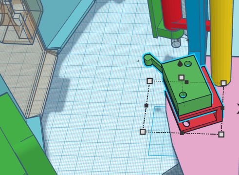
Water basket
The next step is installing the box with water. I used one I got in a grocery store. The reason we put it in place now is that it is large, and all other objects should be placed around it, or at least with it in mind. On the picture you can see click-fit holders that keep the box in place, in an actual device I used glue (which is cheating).

Side brushes
Next, we need side brushes. We use small motors with reductors from Ali, that are surprisingly good for this purpose:


We also use ready side brushes (Ali again):

As you can see, we need a larger hole on the robot's base:

We need to lift the motor so that brush is half-immersed in the base:

Of course, in the production-ready design this "box" should be made smooth, following the shape of the top of a brush. This looks nicer, but doesn't affect anything in terms of usability.
Now, we are going to place a motor on top of that "box" and to cover it with a "holder". That way motor can not move up or down, neither can it spin. We can attach brush to it by simply pushing from below:

This is what side prushes look when they are in place with their motors:

Bumper
The next step is a bumper of course. As was mentioned before, 3d printer has size limitations, so we print parts and then glue them together:

Note that in this design I added 3 slots for ultra sonic sensors. The way they are usually used in "normal" VC is, to detect a wall in advance, and to drop the speed, so instead of a loud collision we have a soft touch. However, to make washer to wipe the floor better, I had to reduce the speed about 3 times, so sensors are not necessary. It moves slow enough already:

Note the way shields of the bumper overlap to increase total rigidness of the structure:

Last shields on the right and left sides have different shape: in theory, it should reduce incidents when the robot turns and left/right end of a bumper hits the obstacle.

In a production-ready unit this sort of incidents should be excluded by precise design:

Bump sensors
Next, we need sensors that detect the fact that bumper was moved. Leaving design specifics aside, they are nothing but clickable buttons:

We are going to install 3 sensors: two on top of wheels at the sides of our robot and one in front.
Side sensors have to be lifted up so that they are on top of the wheel:


When the corresponding side of the bumper hits the obstacle, it moves towards the sensor and presses it, as it is nothing but a pressable button:

As for the front sensor, we lift it just slightly using U-shaped plastic holder. It is located at the center (or almost at the center) of a bumper. The following image shows the central sensor, to make it easier to read, I moved the bumper forward a bit.
Note the "almost" above. It is a common situation in mechanical design, when we need to place more than one device at the center (corner, top etc) of our robot. In our case, the holder of a bumper should be at the center line, as well as the sensor: what should we do?
Well, we should ask ourselves "should it really be EXACTLY at the center line, and if the answer is "no", we should move it few centimeters to the side.
So, as we mentioned the bumper holders, let's discuss them. Earlier, in VC Prototype 1 I "invented" a simple mechanical schematics, allowing the bumper to move as we need it to, and preventing it from swinging to the sides and doing other unwanted sort of things. That design was ok, but printing it (or making it by hand) was tricky and it didn't look nice. So for this project I have "invented" another one, which is kind of nicer. Note the quotes around "invented": I am pretty sure it have been invented many times before me; luckily, I am not using this design to actually produce robots. Otherwise, your patent lawyer should probably make sure it is financially safe.
As you can see, this simple device can extend/collapse along horizontal axe, but is rigid enough to NOT bend up or down: just what we need from our bumper. Once again, we are going to hold bumper "in the air" using 3 devices like at the picture above (left, center and right ones).


If you think about it, this design is insufficient. What if we move the bumper to the side, like at the image we presented earlier?

If the obstacle presses against the end (left or right) of a bumper and we only have holders presented on pictures above, it (the bumper) will slide around the body of a robot... which is not what we want.
So we have to introduce an additional stopper, one preventing the bumper from going sideways:

As you can see, it is a simple restriction we placed around the central bumper holder, nor our bumper can move ONLY as the VC bumper should.
Battery holder
The next thing is a battery holder. Here we have two choices: we can use NiMh accumulators, or we can use Lithium ones. As Lithium cas capacity that is about 3 times higher, the choice seems obvious, but... We are going to use NiMh.
You see, this is a tutorial. And it can be read and implemented by beginners. While Lithium accumulators, when handled wrong, combust. It becomes even worse when you think about water we carry around: humid electronics burns even better. So we stick to a safer accumulators, even though we'll need more of them.
Of course, nothing prevents you from using Lithium accumulators, at your own risk.
Here is a battery compartment. I an going to hold there 8 holders obtained from Ali, with 4 accumulators each:

When fully charged, his battery pack produces 19.2 V (16 batteries in a pack, 1.2 V each battery, 2 packs connected in parallel).
Battery pack:

Battery pack in place:

Note one thing that probably is not obvious: all heavy objects, like battery pack and basket with water, are located in front of the wheels. See, our robot has 3 wheels, and if its back side was heavier, the front wheel would go up, and the robot would "sit". Which is not what we need. So we make sure its weight is between wheels, not behind.
Power switch holder
Now we need to install a holder for the power switch. I use one of countless power switches you can get, so if yours is different, you will have to design something appropriate. What this holder does is keeping the switch raised, so that wires that go to it can be hidden below:


Arduino holder
We are going to use Arduino Uno as a processor for our robot. There are many designs of "holders" for this processor, I took one that allows using bolts, but works fine even without them:

Same holder with Arduino in it:

Arduino in place. As most of parts of our robot, this one is attached to robot's base using glue:

Holder for power convertors
I am going to discuss electronics later in this article. What you need to know right now is, we will need one MT-3608 power convertor and two LM-317 ones. I have designed a simple holter for them, and placed it on top of the left wheel. On the following picture, red rectangle is MT-3608, while gray boxes are LM-317:

Front wheel
One thing I mentioned earlier is the front wheel, a passive (no motor) wheel supporting the front part of our robot. using such wheels is a common design solution in robotic VC, except ours is less elegant. In a production-ready design we probably need to increase its size 2-3, or even 4 times, make a hole in a robot's base and immerse that larger wheel in this hole. The larger the wheel, the less are chances that it will stuck at the edge of a carpet or at a trash holder. Once again, this is a common solution in VC design:

"Real" VC from the store:

The front wheel in place:

Main brush
Next thing is the brush. As you might notice, our robot looks suspiciously similar to a VC, so let's explain some similarities and differences. The main difference is wheels. We don't need to "fight" for sucking power, so we don't have to place our robot as close to the floor as we can. So we do not use springs allowing our wheels to propel the robot while its body literally lies on the floor.
The similarities are bumper, overall round shape and... brushes. We are going to use wet brushes, but the idea of "mopping" the floor with brushes, both side ones and one in the middle, holds. Same way, we want dirt water and occasional dust to be collected in a "dust" bin" we do not use vacuum, but wet brush will pick it from the floor, and as it spins, water will slide off it and to the "dust" bin.
The brush, of course, was bought on Ali:

As usual (as in VC) the brush is covered by a cylindrical box: we don't want drops of dirty water all over our robot as well as around it. Behind the brush, we place a "dust bin", a "dirt water compartment". The very fact that brush rotates helps us to direct water outside and to the compartment. Additionally, we are going to use a spiky "hair collector" to clean the brush (see later).

The brush holder is covered by the lid. As it is very difficult to print brush holder and lid as one part, we print them separately, and connect using glue.

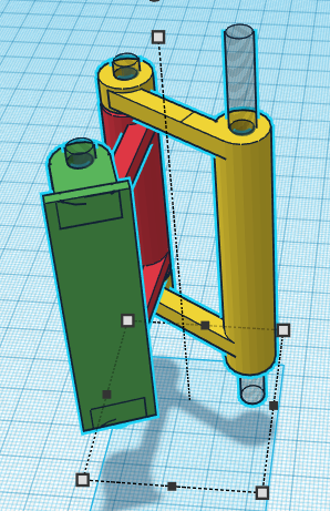
Brush should spin, which means we need a motor and a strong one. Mine I got from an old vacuum cleaner, it is a 24V motor with reductor. You can use anything that is strong enough and spins at 2-4 rps.

Note the way motor is connected to the brush. We can not connect it directly, as we don't have enough space at the side, so we have placed the motor on top. This is, by the way, why the top of a brush holder is made flat. Also, we use 3 gears, not two. See, I am quite happy with the speed of my motor and i do not want to increase it. So gears at the motor and at the brush should be the same size. But...
But if we use large gears, the one at the bottom will scratch the ground! We need a small gear at the bottom, which means we need a small gear on top, too. So we add an "intermediate" gear, its size doesn't affect the resulting speed, so I took what I had. It is a bit too large, so I moved it to the side.
Note the way a motor is held in place.

This approach is not perfect, because after you glue the motor holder to the brush holder, you will not be able to remove the motor, unless the other end of this assembly can be removed easily (I mean using bolts and nuts, instead of glue). So let's take a look at that "other end".
First of all, gears. There are many ways of holding gears: bearings, plastic or metal axes and so on. I chose metal axes. They are 2mm in diameter and can be pressed in the 2.5 mm holes in gears. The reason holes are larger than axes is in specifics of 3d printing: small holes are imprecise, and a 2.5 mm hole is really something like 1.8. Which is exactly what we need to get a rigid result.
You can make axes by cutting nails, but Ali sells a ready ones, 20mm long, which are perfect for our purpose. Also they sell nylon (I think it is nylon) sleeves. So all we need is to put the sleeve in a hole and put an axe through it.


Note the pink base of this installation. We are going to glue it to brush holder.
A gears holder, the "other end" mentioned above, is the red part on a picture above. We use bolts to hold it in place, so everything, including motor, can be easily removed:

The other side of a brush ends with a metal axe 3mm in diameter. All we need is to put it to a printed sleeve:

Brush cleaner
Now about spiky "hair collector" mentioned above. Attached to the brush holder so that spikes are slightly up, it allows water and occasional dust and hair to go from the brush down to a "dirty water collector".

Note that the volume of a collector is much less than one of a water basket, after all, some water remains on the floor. I thought about an obvious way of recycling water by getting it from the basket, to the floor, to collector and through the filter back to basket. Well... This design can work, so if I decide to do it, I will use a small bottle with some cotton, that's all.
The "brush cleaner" (here, I finally came up with the name for it) is attached using glue:

Peristaltic pump
The idea of our cleaning process is to pump some water or cleaning solution under the front brushes, drop by drop, at a reasonably low speed. We are going to achieve it using so called peristaltic pump, a low speed high precision liquid pump. It is possible to print the thing, but they are available at Ali by a really small price, so we better use a factory build device.


To connect the pump with basket of water on one side and with spots on the robot's base, where we want the water to be delivered, we will use 1 mm PTFE pipes (Ali again), splitters (we need to bring water from one pump to two front brushes) and silicon pipe to connect PTFE with splitter:


There are, as usual, many ways of attaching peristaltic pump to a robot. We are going to use "quick and dirty" one: tie the pump to a small rectangular piece of plastic, and glue that plastic to the brush holder. This is probably not the best approach, so in future versions it should be improved.


Connect front and back
Now we use printed connector to join brush compartment with the front part of our robot.


The robot, view from top:

The "real thing":

Electronics
We use the following schematics:

It all begins with 19.2 V power coming from the battery. The power switch has 3 contacts, but any switch that has "on" and "off" will do.

Then we feed this power to 3 power convertors: a step up convertor produces 24V for the main brus motor, and two step down LM-317 convertors provide 9V for Arduino and 6V for small brushes and peristaltic pump.
The use of two types of power convertors is due to the fact that to get 24V we need a step UP convertor, while to get 6 and 9V, we need a step down one.
We use double relay (which means two relay, independent but in one body) to control brushes, one relay for small brushes and another one for a large brush (6 and 24V). Note that in a "real" device I remove realys completely, as brushes should always spin, so there is no real need to control them. Same with a peristaltic pump (it is not shown on the schematics, but if it was, it would be connected to 6V relay, or directly to 6V power converter, parallel to small brushes). Why would we need relays then? For a simple reason: say, we want to make a "smart" floor washer, one that at some point shuts brushes and the pump down and begin looking for a charger. As current implementation doesn't have that functionality, well, no relays.
Arduino controls relays via pins Gnd and 11, if we don't use relays, those wires should not be used (obviously).
Next thing we need to study in details is sensor array. We have 3 buttons (1K each), "pulling" corresponding pins (2, 3 or 4), depending which button is pressed. Buttons can be pressed simultaneously, like front and left ones, why not?
The L293D controller is used to work with motors (wheels). Arduino itself can not provide sufficient current to power up those motors, so this controller takes signals from arduino and power from the power source (rather than from Arduino). Motors are shown next to it, connected to Out1, Out2, Out3, Out4.
Arduino controls L293D via pins 5, 6, 7 and 8, 9, 10, setting the direction wheels rotate and speed. We will discuss it in the programming section.
The only thing that remains to be discussed is the way we power our Arduino. There are few ways, as you can find in the documentation on Arduino site as well as on the net forums. However, feeding power through the barrel is the safest one. So we plug our 9V power to Arduino's "barrel".
Shield for motors controller
Earlier, we discussed the use of L293D controller. Now, we need to connect it to Arduino, motors and power source, and "just wiring" would be messy. We need a shield.
By shield I mean a holder for the chip and (optionally) some of its peripheral electronics, contacts, connectors and so on. In our case we are going to attach shield directly to Arduino, avoiding the need to connect 6 Arduino's pins to the L293D chip.
First, we take a foiled getinax. it is a heat resistant plastic with copper foil glued to it. We use hydrogen peroxide method to remove extra copper:


Programming
Arduino controls our robot, so we need a program to control Arduino. As this is not a programming tutorial, we are not going to implement advances approaches, limiting ourselves to a version of simple bump-and-run algorithm. You can find an algorithm designer on Snowcron Robotics site, so you can create rather complex ones, but... We simply don't need it for a primitive robot like that.
To create a project, download Arduino software from the official site, run arduino.exe and use menu to create a new project. Call it "FloorWasher".
Arduino's project may include few files, one (main) should have an extension ".ino". In our case it is going to be "FloorWasher.ino" Let's examine the code, line by line.
First, we need to include the library (comes with Arduino or can be downloaded from the net) that allows us to control motors via L293D, it includes both speed and rotation direction, as well as acceleration/deceleration to the defined speed. The include file is TrackMotor.h. I am pretty sure I got it from somewhere, rather than writing it, but I wasn't able to find the source.
#ifndef TRACK_MOTOR
#define TRACK_MOTOR

#include "Arduino.h"

enum { MOTOR_FORWARD, MOTOR_BACK };

class TrackMotor
{
    public:
        int m_nEnableMotorPin;
		int m_nRunMotorForwardPin;
		int m_nRunMotorBackPin;

        TrackMotor(int nEnableMotorPin, int nRunMotorForwardPin, int nRunMotorBackPin)
        {
			m_nEnableMotorPin = nEnableMotorPin;
			m_nRunMotorForwardPin = nRunMotorForwardPin;
			m_nRunMotorBackPin = nRunMotorBackPin;

			// ---

            pinMode(m_nEnableMotorPin, OUTPUT);
			pinMode(m_nRunMotorForwardPin, OUTPUT);
			pinMode(m_nRunMotorBackPin, OUTPUT);
	}

        // ---

        void enableMotor(bool bActive)
        {
            digitalWrite(m_nEnableMotorPin, bActive == true ? HIGH : LOW);
        }

		// ---

		void runMotor(int nDirection)
		{
			if(nDirection == MOTOR_FORWARD)
			{
				digitalWrite (m_nRunMotorForwardPin, HIGH);
				digitalWrite (m_nRunMotorBackPin, LOW);
			}
			else if(nDirection == MOTOR_BACK)
			{
				digitalWrite (m_nRunMotorForwardPin, LOW);
				digitalWrite (m_nRunMotorBackPin, HIGH);
			}
            else
				enableMotor(false);
		}

  };

#endif // TRACK_MOTOR
The code is simple: perform current operation until its timer is not over, then make next operation current, and assign a new next operation.
// Include class that wraps motor functionality
#include "TrackMotor.h"

// Possible states of the robot
enum { MOTORS_OFF, MOTORS_ON, MOTORS_FORWARD,
	MOTORS_BACK, MOTORS_LEFT, MOTORS_RIGHT };

// Pins (compare to schematics) controlling motors.
TrackMotor motorLeft(5, 7, 6);
TrackMotor motorRight(8, 10, 9);

class Motors
{
    public:
        // We keep the robot's state and next state.
		// For example, run forward for 10 seconds (current state),
		// then turn left (next state)
        int m_nState;
        int m_nNextState;

        // Max. time to perform the current operation. If we hit
		// an obstacle, the time will be less than max.
        int m_nTimeout;

        // Time when the prev. "update" was. We keep absolute time
		// for the operations (like "turn left for 1 sec.)"
        unsigned long m_nPreviousMillis;

        // Bumper's pushbuttons status
        int m_btnLeftState;
        int m_btnCenterState;
        int m_btnRightState;

		// Pins for the sensors (buttons)
        int m_btnLeftPin;
        int m_btnCenterPin;
        int m_btnRightPin;

        Motors()
        {
            m_nPreviousMillis = 0;

            m_btnLeftState = 0;
            m_btnRightState = 0;

            m_btnLeftPin = 2;
            m_btnRightPin = 3;
            m_btnCenterPin = 4;

            pinMode(m_btnLeftPin, INPUT);
            pinMode(m_btnCenterPin, INPUT);
            pinMode(m_btnRightPin, INPUT);

            m_nTimeout = 0;
            m_nNextState = MOTORS_LEFT;

			// We turn motors on and move forward
            setState(MOTORS_ON);
            setState(MOTORS_FORWARD);
        }

        // ---

        void setState(int nState)
        {
            m_nState = nState;
            switch(m_nState)
            {
                case MOTORS_ON:
                    Serial.println ("Enabling Motors");

                    motorLeft.enableMotor(true);
                    motorRight.enableMotor(true);

                    break;

                case MOTORS_FORWARD:
                    Serial.println ("Motors Forward");

                    // Go forward for max. 20 seconds
                    m_nTimeout = 20000;

                    motorLeft.runMotor(MOTOR_FORWARD);
                    motorRight.runMotor(MOTOR_FORWARD);

                    break;

                case MOTORS_BACK:
                    Serial.println ("Motion Backwards");
                    m_nTimeout = 500;

                    motorLeft.runMotor(MOTOR_BACK);
                    motorRight.runMotor(MOTOR_BACK);

                    break;

                case MOTORS_LEFT:
                    Serial.println ("Turning Left");
                    m_nTimeout = 1000;

                    motorLeft.runMotor(MOTOR_BACK);
                    motorRight.runMotor(MOTOR_FORWARD);

                    break;

                case MOTORS_RIGHT:
                    Serial.println ("Turning Right");
                    m_nTimeout = 1000;

                    motorLeft.runMotor(MOTOR_FORWARD);
                    motorRight.runMotor(MOTOR_BACK);

                    break;

                case MOTORS_OFF:
                default:
                    Serial.println ("Disabling Motors");

                    motorLeft.enableMotor(false);
                    motorRight.enableMotor(false);

                    break;
            }
        }

        // ---

        void update()
        {
            unsigned long currentMillis = millis();
            if(m_nPreviousMillis == 0)
                m_nPreviousMillis = currentMillis;

            // If the pushbutton is pressed, buttonState is HIGH.
            // Whatever happens, we begin by moving back.
            if(m_btnLeftState == HIGH)
			{
				Serial.println ("Left button pressed: Moving Back");
                m_nPreviousMillis = currentMillis;
                m_nNextState = MOTORS_RIGHT;
                setState(MOTORS_BACK);
            }
            else if(m_btnCenterState == HIGH)
			{
			Serial.println ("Central button pressed: Moving Back");
					m_nPreviousMillis = currentMillis;
					m_nNextState = MOTORS_LEFT;
					setState(MOTORS_BACK);
            }
            else if(m_btnRightState == HIGH)
			{
			Serial.println ("Right button pressed: Moving Back");
					m_nPreviousMillis = currentMillis;
					m_nNextState = MOTORS_LEFT;
					setState(MOTORS_BACK);
				}
            else if(m_btnLeftState == LOW && m_btnCenterState == LOW
				&& m_btnRightState == LOW
                && currentMillis - m_nPreviousMillis >= m_nTimeout)
            {
                int nState = m_nNextState;

                if(m_nState == MOTORS_LEFT || m_nState == MOTORS_RIGHT)
                {
                    Serial.println ("Buttons released");
                    m_nNextState = MOTORS_FORWARD;
                }
                else if(m_nState == MOTORS_BACK)
                {
                    Serial.println ("Finished going back");
                    m_nNextState = MOTORS_FORWARD;
                }
                else if(m_nState == MOTORS_FORWARD)
                {
                    Serial.println ("Finished going back");
                    m_nNextState = MOTORS_LEFT;
                }

                m_nPreviousMillis = currentMillis;

                setState(nState);
            }
        }

} motors;

// ---

void setup()
{
    Serial.begin (9600);
}

// ---

void loop()
{
    motors.m_btnLeftState = digitalRead(motors.m_btnLeftPin);
    motors.m_btnCenterState = digitalRead(motors.m_btnCenterPin);
    motors.m_btnRightState = digitalRead(motors.m_btnRightPin);

    motors.update();
}
