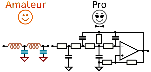
The idea to build a 4th order low-pass filter looks simple: add one more feedback loop. But there are pitfalls, as always.
Basic equations for fourth order low-pass filters
The transfer function of a 4th order low-pass filter is:
                             A
H(s) = ———————————————————————————————————————————————
       (1 + s/(Q₁ ω₁) + s²/ω₁²)(1 + s/(Q ω₂) + s²/ω₂²)
where:
A – DC gain;
ω₁ – radial frequency of the first stage, K1 × ω;
ω₂ – radial frequency of the second stage, K2 × ω;
Q₁ – quality factor of the first stage;
Q₂ – quality factor of the second stage;
ω – pass-band radial frequency of the filter;
s – complex frequency.
Open brackets to get another form of the transfer function:
                          A
H(s) = ———————————————————————————————————————
       1 + ps1 s + ps2 s^2 + ps3 s^3 + ps4 s^4

ps1 = 1 / (Q₁ ω₁) + 1 / (Q₂ ω₂)
ps2 = 1 / (Q₁ ω₁ Q₂ ω₂) + 1/ω₁² + 1/ω₂²
ps3 = 1 / (Q₁ ω₁ ω₂²) + 1 / (ω₁² Q₂ ω₂)
ps4 = 1 / (ω₁² ω₂²)
Knowing −3 dB frequency and filter type, we can get K1, Q1, K2 and Q2 from tables in books [1] or compute them.
Circuits
Let’s start by adding one more feedback loop to well-known Multiple Feedback (MFB) and Sallen-Key (SK) second order low-pass filter topologies.
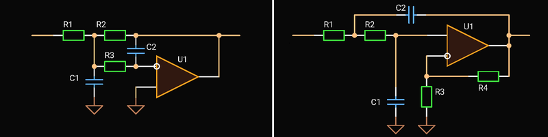 |
| Second Order Topologies |
 |
| Fourth Order Topologies |
Write equations and try to solve them.
Surprise: there are no solutions with positive component values. Varying gain, it turns out that there are solutions only for the Sallen-Key topology when gain is more than 3.
The equations for MFB look like:
psN = a + b + c + d
The equations for SK look like:
psN = a + b + c − d
So, possible, we need to find a way to add members with the negative sign to the equations.
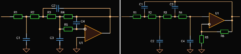
4-th Order One Op Amp Sallen-Key Low-pass Filter
For SK, a resistor divider helps. Now the equations have solutions with gains around 1.
 |
| Fourth Order Sallen-Key Low-pass Filter |
Design Equations
The transfer function is:
                          A
H(s) = ———————————————————————————————————————
       1 + ps1 s + ps2 s^2 + ps3 s^3 + ps4 s^4
Assuming an ideal Op Amp, the factors are:
      R6 (C1 R1 (R2 + R3) + C2 (R1 + R2) (R3 + R4) + C4 (R4 R5 + (R1 + R2 + R3) (R4 + mR5)))
      − R4 R7 (C1 R1 + C3 (R1 + R2 + R3))
ps1 = ——————————————————————————————————————————————————————————————————————————————————————
                                      (R1 + R2 + R3 + R4) R6
      R6 (R1 C1 (R2 C2 (R3 + R4) + C4 ((R2 + R3 + R4) R5 + (R2 + R3) R4))
      + C4 (C2 (R1 + R2) ((R3 + R4) R5 + R3 R4) + R4 R5 C3 (R1 + R2 + R3)))
      − C3 R4 R7 (R1 C1 (R2 + R3) + R3 C2 (R1 + R2))
ps2 = —————————————————————————————————————————————————————————————————————
                           (R1 + R2 + R3 + R4) R6
      C4 R6 (R1 R2 C1 C2 (R4 R5 + R3 (R5 + R4)) + R4 R5 C3 (C1 R1 (R2 + R3) + R3 C2 (R1 + R2)))
      − R1 R2 R3 R4 R7 C1 C2 C3
ps3 = —————————————————————————————————————————————————————————————————————————————————————————
                                       (R1 + R2 + R3 + R4) R6
      R1 R2 R3 R4 R5 R6 C1 C2 C3 C4
ps4 = —————————————————————————————
         (R1 + R2 + R3 + R4) R6
the DC gain is:
    R4 (R7 / R6 + 1)
A = —————————————————
    R1 + R2 + R3 + R4
But there is another problem: the circuit is very sensitive to component tolerances.
A fourth order Butterworth filter circuit is shown with a pass-band of 1 kHz and a gain of 2 with computed and the closest standard component values.
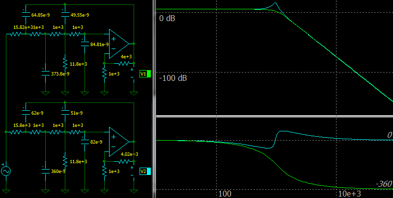 |
| 4 Pole Sallen-Key Low-pass Filter, Simulation |
Thus, this 4th pole SK topology is useless in practice. Drop it.
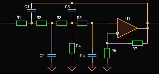
4-th Order One Op Amp Multiple Feedback Low-pass Filter
For MFB topology, members with negative signs can be added with positive feedback.
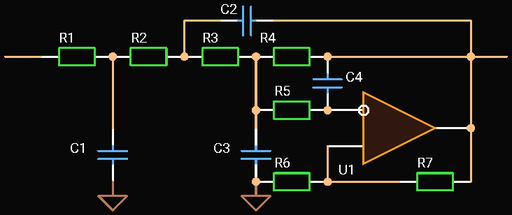 |
| 4-th Order Multiple Feedback Low-pass Filter |
Design Equations
The transfer function is:
                          A
H(s) = ———————————————————————————————————————
       1 + ps1 s + ps2 s^2 + ps3 s^3 + ps4 s^4
Assuming an ideal Op Amp, the factors are:
      R7 (R1 C1 (R2 + R3) + C2 (R1 + R2) (R3 + R4) + C4 (R4 R5 + (R4 + R5) (R1 + R2 + R3)))
      − R4 R6 (C1 R1 + C3 (R1 + R2 + R3))
ps1 = —————————————————————————————————————————————————————————————————————————————————————
                                 (R1 + R2 + R3) R7 − R4 R6
      R7 (R1 R2 C1 C2 (R3 + R4) + C4 (R1 C1 (R4 R5 + (R2 + R3) (R4 + R5))
      + C2 (R1 + R2) (R4 R5 + R3 (R4 + R5)) + R4 R5 C3 (R1 + R2 + R3)))
      − C3 R4 R6 (C1 R1 (R2 + R3) + C2 R3 (R1 + R2))
ps2 = ———————————————————————————————————————————————————————————————————
                           (R1 + R2 + R3) R7 − R4 R6
      R7 C4 (R1 R2 C1 C2 (R4 R5 + R3 (R4 + R5)) + R4 R5 C3 (R1 C1 (R2 + R3) + R3 C2 (R1 + R2)))
      − R1 R2 R3 R4 R6 C1 C2 C3
ps3 = —————————————————————————————————————————————————————————————————————————————————————————
                                   (R1 + R2 + R3) R7 − R4 R6
      R1 R2 R3 R4 R5 R7 C1 C2 C3 C4
ps4 = —————————————————————————————
        (R1 + R2 + R3) R7 − R4 R6
the DC gain is:
            R3 (R6 + R7)
A = − —————————————————————————
      (R1 + R2 + R3) R7 − R4 R6
Example
Let’s compute a unity gain fourth order Butterworth filter with 150 kHz pass-band.
Set
The DC gain now is:
            R3 (R6 + R7)              R (R6 / R7 + 1)
A = − ————————————————————————— = − ————————————————————
      (R1 + R2 + R3) R7 − R4 R6     R1 + R (2 − R6 / R7)
Thus,
Choose
     (A (2 − R6 / R7) − 1 − R6 / R7) R   (−1 × (2 − 2) − 1 − 2) × 1 kOhm
R1 = ————————————————————————————————— = ——————————————————————————————— = 3000 ≈ 3.01 kOhm (E96)
                      A                                 −1
For a 4th order Butterworth filter
         1         1                  1                           1
ps1 = ——————— + ——————— = ————————————————————————— + ————————————————————————— ≈ 2.773e-6
      Q₁ K1 ω   Q₂ K2 ω   0.5412 × 1 × 2π × 150 kHz   1.3066 × 1 × 2π × 150 kHz

             1             1        1                              1                                      1                   1
ps2 = ——————————————— + ——————— + —————— = ————————————————————————————————————————————————————— + ————————————————— + —————————————————— ≈ 3.834e-12
      K1 ω Q₁  K2 ω Q₂  (K1 ω)²   (K2 ω)²  1 × 2π × 150 kHz × 0.5412 × 1 × 2π × 150 kHz × 1.3066   (1× 2π ×150 kHz)²   (1 × 2π × 150 kHz)²

             1                 1                              1                                                1
ps3 = ——————————————— + ——————————————— = ———————————————————————————————————————————— + ——————————————————————————————————————————————— ≈ 3.121e-18
      Q₂ K2 ω (K1 ω)²   Q₁ K1 ω (K2 ω)²   1.3066 × 1 × 2π × 150 kHz × (1×2 π×150 kHz)²   0.5412 × 1 × 2π × 150 kHz × (1 × 2π × 150 kHz)²

           1                           1
ps4 = ———————————— = —————————————————————————————————————— ≈ 1.267e-24
      (K1 ω K2 ω)²   (1 × 2π × 150 kHz × 1 × 2π × 150 kHz)²
There are 4 equations and 5 unknown values: C1, C2, C3, C4, R5.
We can set an R5 value and solve the equations numerically to find C1, C2, C3, C4.
Let’s set
The solution is:
C1 ≈ 1.341 nF ≈ 1.3 nF (E24)
C2 ≈ 1.286 nF ≈ 1.3 nF (E24)
C3 ≈ 1.782 nF ≈ 1.8 nF (E24)
C4 ≈ 2.677 nF ≈ 2.7 nF (E24)
Simulation confirms that the solution is correct and that sensitivity to component tolerances is acceptable.
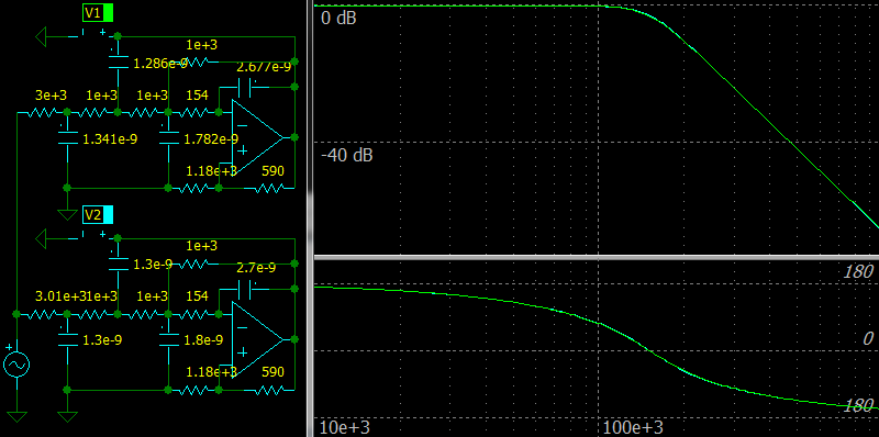 |
| 4-th Order Multiple Feedback Low-pass Filter, Frequency response |
Magnitude of the input impedance is defined by the R1 value.
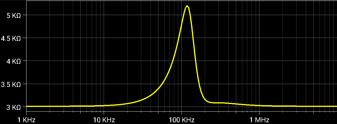 |
| 4-th Order Multiple Feedback Low-pass Filter, Input impedance |
Step response confirms that the circuit is stable. An Op Amp model with unity gain frequency of 8 MHz and DC gain of 120 dB is used. Parasitic capacitances at inputs are added to do it more realistic.
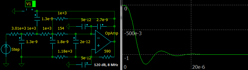 |
| 4-th Order Multiple Feedback Butterworth Low-pass Filter, Step response |
Conclusion
A 4th order low-pass filter can be designed using only one Op Amp. All filters parameters are linked, so sensitivity to component tolerances should be verified.
Sensitivity of the 4th order Sallen-Key topology to component tolerances is too high, so this topology cannot be recommended to use.
If relatively high output impedance is acceptable, an RC network can be added at the output to get a 5th order low-pass filter.
Unfortunately, I could not find a solution with Fully Differential Amplifier.
