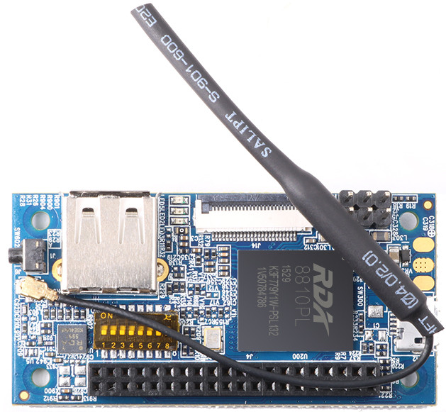
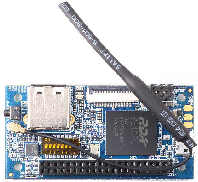
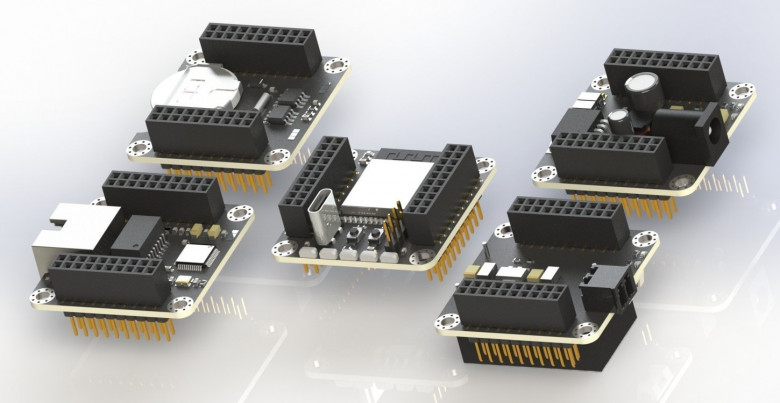
In this article I will talk about my attempt to create flexible, compact and beautiful modular prototyping framework
Learning how to program microcontrollers
In this article I will talk about my attempt to create flexible, compact and beautiful modular prototyping framework
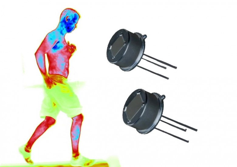
In this article, there is the work with the PYD 1588 digital Infrared passive motion sensor introduced. The PYD 1588 is a serial opposed format, two element detector based on pyroceramic produced by the Excelitas Technologies. This sensor represents a low-power (3.0 uA with 1.8 V source voltage as in the documentation said) passive component with two sensible elements, which measure the thermal infrared radiation stream.
The signal is converted to a digital value using Sigma-Delta and DSP techniques. A configurable motion detection unit is implemented, which can generate an interrupt recognized by the external microcontroller (MCU) in case motion is detected. The motion detection unit contributes to significant device energy efficiency increasing via putting the MCU to a low-power sleep mode with no periodic raw data request and its analyzing necessity.
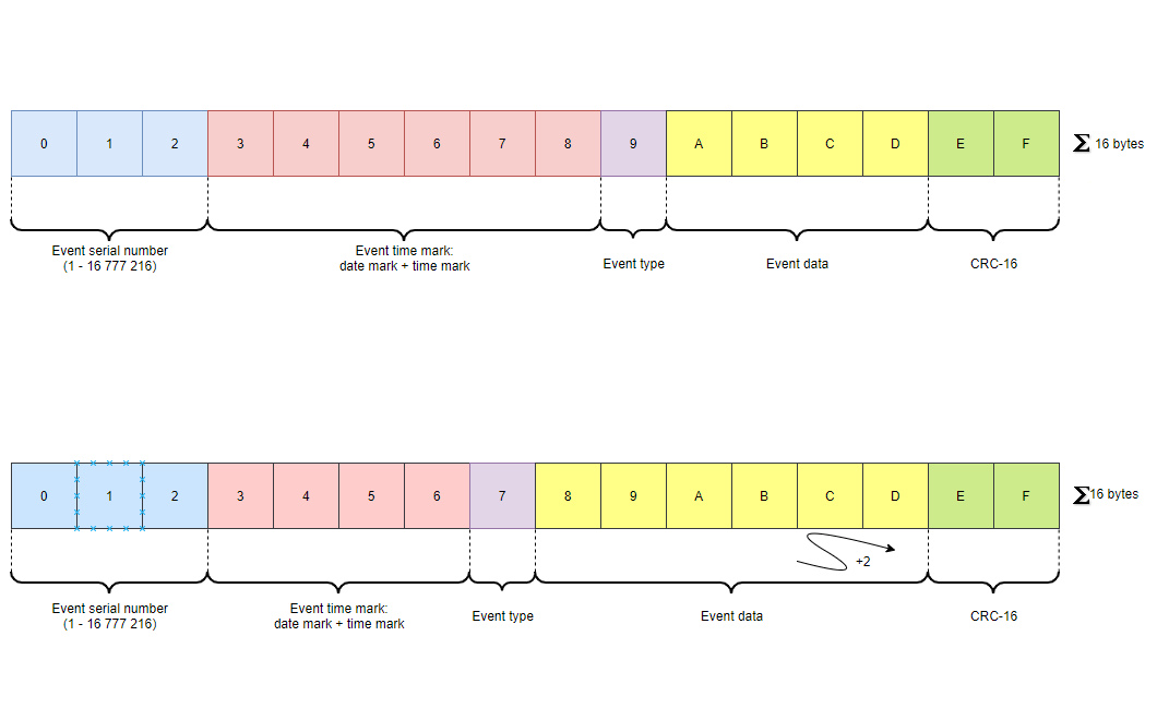
The Real-Time Clock (RTC) Calendar Registers in STM32 microcontrollers implemented in Binary Code Decimal format (BCD) i. e., every two digits are represented by one byte (low digit in 0-3 bits and high digit 4-7 bits). At least there are 5 bytes required to store date and time data in a such format. There are cases when memory allocation for time stamp might become critical, e. g., the events log keeping in an extern non-volatile memory IC. Here the memory value for a single event (event serial number, timestamp, event parameters, and its CRC) is fixed and can compose up to 16 bytes. The maximum quantity of the events increasing, and time spent on a single operation reducing (for reserved power sources as supercapacitors and electrolytic capacitors is critical) can be achieved with less memory amount required for the event field.
Ссылка на русскую версию / link to Russian version
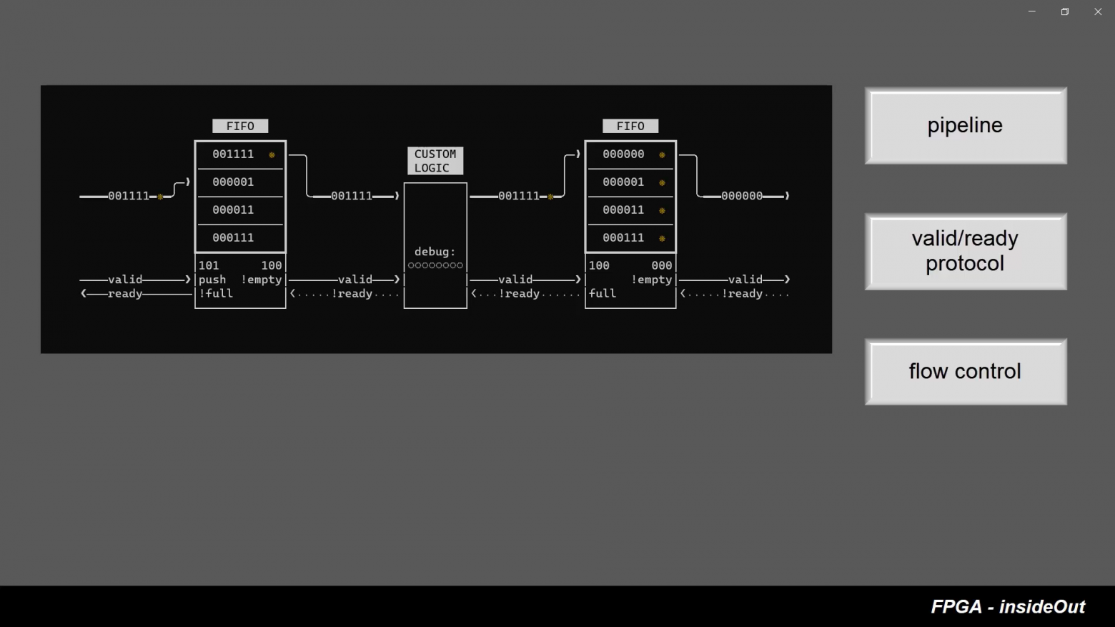
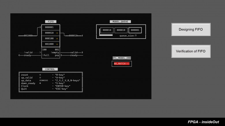
FPGA InsideOut is an attempt to make a set of educational FPGA videos presented in the “human-in-the-loop” style. In these videos we will not only show how we are interfacing with an actual FPGA board but will also provide synchronous real-time visualisation of FPGA's internal logic.
For our first video we have picked a CRC circuit (cycle redundancy check) which is based on a linear feedback shift register. This circuit goes through several transformations during the course of the video. Intrigued? - let’s watch the video.
Flipper Zero is an open-source multi-tool for geeks and penetration testers. It so happened that the Flipper Zero project and the PVS-Studio analyzer crossed paths. A philosophical question: should we check the project, if the project developers have already started fixing errors? Let's try to do this.
Demid Efremov and Ivan Kornienko.
Music box on Verilog HDL for Cyclone IV.
Hi there! A while ago, Positive Technologies published the news that ATMs manufactured by Diebold Nixdorf (previously known as Wincor), or more specifically, the RM3 and CMDv5 cash dispensers, contained a vulnerability which allowed attackers to withdraw cash and upload modified (vulnerable) firmware. And since my former colleague Alexei Stennikov and I were directly involved in finding this vulnerability, I would like to share some details.
A couple of years ago the PVS-Studio analyzer got its first diagnostic rules to check program code compliance with the MISRA C and MISRA C++ standards. We collected feedback and saw that our clients were interested in using the analyzer to check their projects for MISRA compliance. So, we decided to further develop the analyzer in this direction. The article covers the MISRA C/C++ standard and the MISRA Compliance report. It also shows what we already managed to do and what we plan to achieve by the end of the year.
This year ChipEXPO conference in Moscow invited several Western speakers to present in English the emerging technologies in high-level HDLs, formal verification, open-source EDA and using industrual RISC-V cores for education. You can join these presentations on September 14-16 for free using this link (you may need to use google translate from Russian to go through the registration) https://eventswallet.com/en/events/282/
The whole program is here
The English-speaking presentations and tutorials include:
Hi from RaccoonLab, a team of enthusiasts in field robotics! We want to share our true-HITL UAVCAN-based simulator for PX4.
We believe a unified UAVCAN bus for drone onboard electronics will become a mainstream approach shortly. Our simulator is already based on UAVCAN (in opposition to UART-MAVLINK) and emulates exactly the same messages as real UAVCAN-sensors.
If you are strongly interested in MISRA and would like to understand whether your project meets one of the MISRA association's standards, there is a solution. It's name is MISRA Compliance. PVS-Studio has recently learned how to generate the MISRA Compliance report. This article describes how you can use this feature. This can make somebody's life better.
Protocol AXI4 was developed for High-bandwidth and low latency applications. It is designed to allow communication between master and slave devices. Master is typically a DMA or CPU and slaves are DRAM controllers, or other specific protocol controllers: UART, SPI, and others. Sometimes one component can implement multiple instances of this protocol. Usually, a prefix is used to differentiate between multiple AXI4 interfaces.
For example, Ethernet MAC can integrate DMA and slave interface used to command MAC. MAC can accept commands on the slave interface that contain data about the location of the next ethernet packet and MAC can start fetching this packet using the separate master interface instance.
This article was motivated by common design mistakes AXI4 designers make when they are designing their Digital IP. (Looking at you Xilinx)
As already described in the previous article, in the process of reworking the DSO138 oscilloscope toy, the idea arose in the DSO303 firmware at some point to try to double the maximum sampling frequency to achieve scanning times of 500 and 200 nanoseconds per cell. In fact, for the STM32F303, the theoretically maximum achievable sampling rate from the point of view of the ADC input, and this is determined by the minimum opening time of the ADC sampling unit, which in our case is 1.5 clock cycles x (1/72 MHz) = 20.8 nanoseconds, is 48 MSPS (millions of counts per second). However, with the parallel operation of 4 ADCs at 6 MHz, it is possible to achieve only 24 MSPS due to the limited speed of the ADC.
Let's imagine that we are considering correctly-periodic signal, which is also constant, i.e. it does not experience fluctuations in frequency and amplitude over time. Is it possible to somehow digitize it not in one, but in several passes, thereby increasing the effective sampling frequency?
On Ali, an interesting toy – an oscilloscope called DSO138 is sold for a very inexpensive price. It has already gained quite a lot of popularity among electronics lovers, but the parameters of this device, alas, allow it to be more or less fully used only for debugging very low-frequency circuits. Actually, it is not positioned as a tool, but rather as a DIY-kit for novice electronics engineers.
This "toy" oscilloscope is assembled on the STM32F103 microcontroller, and with a fairly competent circuit design of the digital part, the presence of a fairly decent 320X240-dot color display, and not the most rotten analog path, everything, alas, is ruined by very weak ADCs on board the 32F103. The claimed band of 200 kHz can be recognized as such only with a very large stretch. Yes, it will show the presence or absence of a signal with such a frequency, but it will not be possible to really look at something beyond this.
At the same time, the 103-series has a slightly more powerful brother - the STM32F303, it is almost completely compatible with the legs, but it is significantly better in terms of the parameters we are interested in, there are 4 ADCs on board with a conversion frequency of 5 MHz (6 MHz with a 10-bit resolution). In this scenario, if you use all 4 ADCs in parallel with a 10-bit resolution, you can get a effective resolution of up to an honest 24 MSPS (millions of samples per second). The microcontroller is also inexpensive; you can easily find it on the same Ali for very reasonable money again. It is clear that the idea to change the microcontroller arose almost immediately after I tried this DSO138.
At the same time, if upgraded the toy can turn out to be a completely full-fledged tool that even professionals, not just novice amateurs, could already use. With these thoughts in mind, I decided to try to do something with a Chinese toy in my free time.
There are many situations when you need to protect your data, and different tools can be used to do that. For example, a safe. We develop a passcode data protection mechanism by using an FPGA board and Quartus Prime software. It allows demonstrating the basic concepts of a combination lock such as entering data, setting and checking a passcode, and displaying data.
The FT4232H is USB 2.0 High speed to UART IC converter. The FT4232H has four UART ports and one USB port.
By connecting EEPROM memory to this chip, you can set specific operating modes or change the manufacturer's data.
Let's look at the example and configure FT4232H directly on a system running GNU/Linux. We will do this using the ftdi_eeprom
.
Information