
LC ladder component values can have different values for the same transfer function. Published tables have only one set. Why?
Arduino, DYI and how to assemble electronics
LC ladder component values can have different values for the same transfer function. Published tables have only one set. Why?
There is a list of well-known electronics design tools for Android which can be found in every review for the last 10 years: “Electrodoc”, “Every Circuit”, “Droid Tesla”, “Electronics Toolbox”, “RF & Microwave Toolbox” and so on. Also, there is a lot of trash on the market that turns finding a good tool into a quest.
This short review is about an unknown but cool tool “Circuit Calculator” working on Android devices and intended for professional electronics designers.
Ссылка на русскую версию / link to Russian version
FPGA InsideOut is an attempt to make a set of educational FPGA videos presented in the “human-in-the-loop” style. In these videos we will not only show how we are interfacing with an actual FPGA board but will also provide synchronous real-time visualisation of FPGA's internal logic.
For our first video we have picked a CRC circuit (cycle redundancy check) which is based on a linear feedback shift register. This circuit goes through several transformations during the course of the video. Intrigued? - let’s watch the video.
In this video, we are making a cable for connecting a quadrature encoder to a Servosila brushless motor controller, and and then running a servo motor in Direct Drive mode. To make the cable we are using a cable assembly kit that can be purchased from the internet store. Alternatively, the components for the cable can be bought in other places. The part numbers are given in the controller's datasheet.
The cable assembly kit consists of a connector and a set of wires with pre-crimped socket blades. If you have a crimper tool, you can also attach the socket blades to wires by yourself.
Lets open a datasheet document that comes with the brushless motor controller. Note that each connector has its first pin clearly marked with a "1" sign. Conventionally, the numbering of pins is done in such a way that there are rows of odd-numbered and even-numbered pins.
The quadrature encoder's electrical interface has 5 wires in total. Positions of the pins of each of the wires are given in the table. The socket blades need to be pushed into the connector until you feel a "click". The blades lock into the connector's sockets. Optionally, primarily for cosmetic reasons, you may want to add a heat-shrink tubing to your cable.
The brushless motor controllers come in two distinct forms, a circular and a rectangular one. Both models are identical in terms of capabilities, features, firmware, and external electrical connectors.
The connector has a locking mechanism that keeps it in place. I soldered a mating connector to the other side of the cable - a connector that my brushless motor needs. Note that your motor will likely require a different connector, or no connector at all. It is always a good idea to test an end-to-end integrity of the cable and its connectors. Lets buzz the wires using a multimeter. The cable is ready.
SEPIC-Ćuk split-rail converter can be used to make positive and negative supplies from a single input voltage for relatively well-matched loads like operational amplifiers.
Transient models are time consuming. Average models reduce modeling time drastically.
The PWM switch average models for current- and voltage-mode are described in details in Christophe Basso’s book “Switch-Mode Power Supplies, Second Edition: SPICE Simulations and Practical Designs”. Using of these models for SEPIC and Ćuk converters is also shown.
This text shows how to use the PWM switch average model to design a split-rail SEPIC-Ćuk converter.
Knowing parameters of small-signal control-to-output transfer functions makes it easier for engineers to design compensation networks of DC/DC converters. The equations for SEPIC can be found in different works and Application Notes, but there are differences. A work has been done to solve this problem.
Simplified design equations for SEPIC with Current Mode control (CM) in Continuous Conduction Mode (CCM) suitable for practical design of compensation networks are shown.
In this video, we will look at how to connect brushless motor controllers to a Linux computer. Specifically, we will use a computer running Debian. The same steps would work for Ubuntu Linux and other Linux distributions derived from Debian.
I've got a small sensorless brushless motor, and a bigger brushless motor with a built-in absolute encoder. Lets look at how to control those from my Debian Linux computer. Servosila brushless motor controllers come in several form factors with either a circular or a rectangular shape. The controllers come with a set of connectors for motors and encoders as well as for USB or CANbus networks.
The controllers can be powered by a power supply unit or by a battery. To spice up my setup, I am going to use a battery to power the controllers and thus their motors. The controllers need 7 to 60 volts DC of voltage input. If I connect the battery, the controllers get powered up. The small LED lights tells us that the controllers are happy with the power supply.
We need to connect the brushless motor controllers to the Linux computer. There are two ways to do that - via CANbus or via USB. Lets look at the USB option first. A regular USB cable is used. Only one of the controllers needs to be connected to a computer or a PLC.
Next, we need to build an internal CANbus network between the controllers. We are going to use a CANbus cross-cable to interconnect the controllers. Each controller comes with two identical CANbus ports that help chain multiple controllers together in a network. If one of the interconnected brushless motor controllers is connected to a computer via USB, then that particular controller becomes a USB-to-CANbus gateway for the rest of the network. Up to 16 controllers can be connected this way via a single USB cable to the same control computer or a PLC. The limit is due to finite throughput of the USB interface.
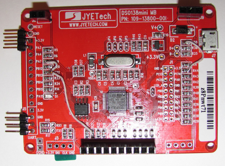
On Ali, an interesting toy – an oscilloscope called DSO138 is sold for a very inexpensive price. It has already gained quite a lot of popularity among electronics lovers, but the parameters of this device, alas, allow it to be more or less fully used only for debugging very low-frequency circuits. Actually, it is not positioned as a tool, but rather as a DIY-kit for novice electronics engineers.
This "toy" oscilloscope is assembled on the STM32F103 microcontroller, and with a fairly competent circuit design of the digital part, the presence of a fairly decent 320X240-dot color display, and not the most rotten analog path, everything, alas, is ruined by very weak ADCs on board the 32F103. The claimed band of 200 kHz can be recognized as such only with a very large stretch. Yes, it will show the presence or absence of a signal with such a frequency, but it will not be possible to really look at something beyond this.
At the same time, the 103-series has a slightly more powerful brother - the STM32F303, it is almost completely compatible with the legs, but it is significantly better in terms of the parameters we are interested in, there are 4 ADCs on board with a conversion frequency of 5 MHz (6 MHz with a 10-bit resolution). In this scenario, if you use all 4 ADCs in parallel with a 10-bit resolution, you can get a effective resolution of up to an honest 24 MSPS (millions of samples per second). The microcontroller is also inexpensive; you can easily find it on the same Ali for very reasonable money again. It is clear that the idea to change the microcontroller arose almost immediately after I tried this DSO138.
At the same time, if upgraded the toy can turn out to be a completely full-fledged tool that even professionals, not just novice amateurs, could already use. With these thoughts in mind, I decided to try to do something with a Chinese toy in my free time.
Space exploration was always fascinating, and recent developments have reignited the interest to the heights never seen since the last man stood on the Moon. People argue about Mars exploration and features of spaceships as their grandparents would’ve done if the internet existed fifty years ago. I’m an electronics engineer working in the aerospace industry, so I know a thing or two about the technical background of this stuff — and I see that these things aren’t common knowledge, and people often have significantly skewed ideas about the reasons behind many things and decisions. Namely, I’d love to speak of some misconceptions about radiation hardened integrated circuits and the means of protection from radiation-induced damage.
I made the “electric” designer of… cardboard. Alas, the project still remains at the prototype stage, not developing into an industrial “physical” look and is waiting for its time (and investor).
But I decided to go further — once we started making cardboard, we’ll bring the situation to its logical conclusion — we’ll make a complete cardboard board game, but with an electric setting and a learning effect. There were a lot of options — starting from a simple “walker” and ending with Ameritrash from a zombie with electron movement and vicious short circuits and swollen capacitors.
As a result, I decided to dwell on a logical abstract, since the schematics of electrical circuits are very suitable for it. Said and done — as a result of the first iteration, the game “Circuit” was born.
If you have dabbled into microchip photographing before, then this article will probably not offer much to you. But if you want to get into it, but don’t know where to start, then it’s exactly for you.
Before we start, a fair warning: while the procedure is quite entertaining, at first it’ll probably be physically painful. The chemicals used during the process are toxic, so please handle them carefully – that way it’ll still hurt, but less so. Also, if you have even a slight amount of common sense, conduct the procedure in a fully-equipped chemical laboratory under supervision of trained professionals: we’ve had to deal with people who tried to do it at home immediately after reading the guide. And finally: if you don’t know whether you need to pour acid into water or water into acid without a Google search and don’t realize what this lack of knowledge will entail – stop reading this immediately and go to a chemistry 101 course in a local college or something.
Information