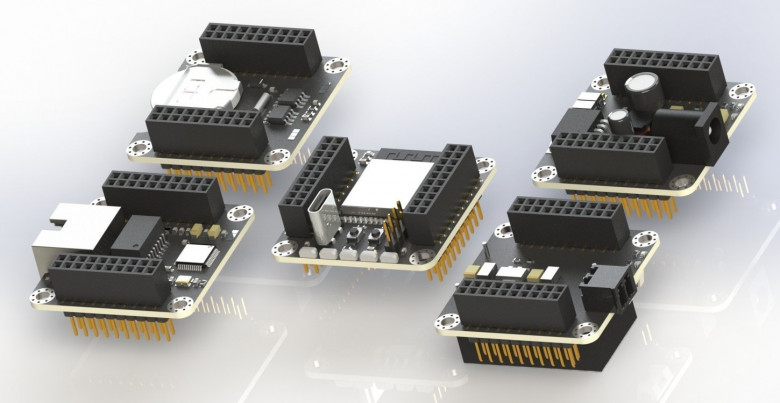
In this article I will talk about my attempt to create flexible, compact and beautiful modular prototyping framework
How to establish a process
In this article I will talk about my attempt to create flexible, compact and beautiful modular prototyping framework
The sound of rock music, in particular of hard rock and heavy metal, is largely based on a specially distorted guitar sound, for which electronic “distortion” devices, tube amplifiers in “overloaded” mode, computers with appropriate software and digital processors are used. increasingly using neural network algorithms.
The distorted sound of electric guitars began to gain popularity around the 1960s. Since that time, the sound of overloaded tube amplifiers, connected to powerful dedicated guitar speakers with large dedicated speakers, has been considered the benchmark in rock music. But tube amplifiers were relatively expensive and inconvenient to operate. Therefore, semiconductor distortion devices were developed.
At that time, the electrical circuitry of distortion devices was relatively simple and the signal output from their output only vaguely resembled the sound of an overloaded tube amplifier. Nevertheless, it was still somewhat similar to the “sound of a lamp” and this provided a powerful incentive for designers of analog semiconductor distortion circuits to continue their research, complicate circuits and propose new circuit solutions. The heyday of analog solid-state distortion was around 1995-2010. The most popular were electrical circuit diagrams like those shown in the figure below.
LC ladder component values can have different values for the same transfer function. Published tables have only one set. Why?
There is a list of well-known electronics design tools for Android which can be found in every review for the last 10 years: “Electrodoc”, “Every Circuit”, “Droid Tesla”, “Electronics Toolbox”, “RF & Microwave Toolbox” and so on. Also, there is a lot of trash on the market that turns finding a good tool into a quest.
This short review is about an unknown but cool tool “Circuit Calculator” working on Android devices and intended for professional electronics designers.
Ссылка на русскую версию / link to Russian version
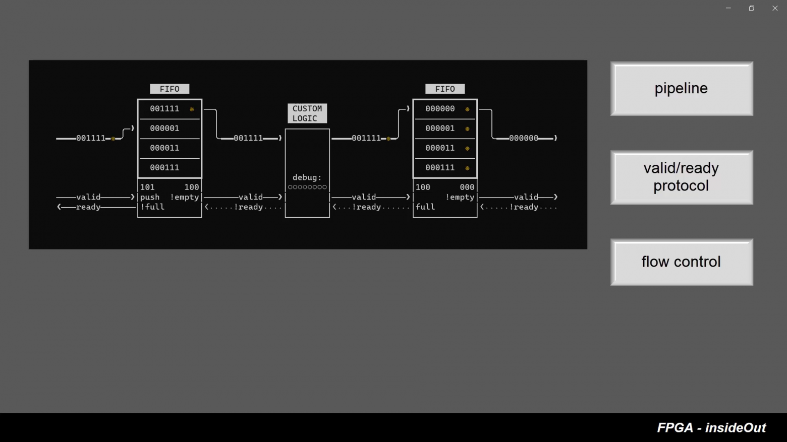
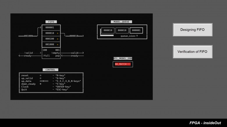
FPGA InsideOut is an attempt to make a set of educational FPGA videos presented in the “human-in-the-loop” style. In these videos we will not only show how we are interfacing with an actual FPGA board but will also provide synchronous real-time visualisation of FPGA's internal logic.
For our first video we have picked a CRC circuit (cycle redundancy check) which is based on a linear feedback shift register. This circuit goes through several transformations during the course of the video. Intrigued? - let’s watch the video.
In this video, we are making a cable for connecting a quadrature encoder to a Servosila brushless motor controller, and and then running a servo motor in Direct Drive mode. To make the cable we are using a cable assembly kit that can be purchased from the internet store. Alternatively, the components for the cable can be bought in other places. The part numbers are given in the controller's datasheet.
The cable assembly kit consists of a connector and a set of wires with pre-crimped socket blades. If you have a crimper tool, you can also attach the socket blades to wires by yourself.
Lets open a datasheet document that comes with the brushless motor controller. Note that each connector has its first pin clearly marked with a "1" sign. Conventionally, the numbering of pins is done in such a way that there are rows of odd-numbered and even-numbered pins.
The quadrature encoder's electrical interface has 5 wires in total. Positions of the pins of each of the wires are given in the table. The socket blades need to be pushed into the connector until you feel a "click". The blades lock into the connector's sockets. Optionally, primarily for cosmetic reasons, you may want to add a heat-shrink tubing to your cable.
The brushless motor controllers come in two distinct forms, a circular and a rectangular one. Both models are identical in terms of capabilities, features, firmware, and external electrical connectors.
The connector has a locking mechanism that keeps it in place. I soldered a mating connector to the other side of the cable - a connector that my brushless motor needs. Note that your motor will likely require a different connector, or no connector at all. It is always a good idea to test an end-to-end integrity of the cable and its connectors. Lets buzz the wires using a multimeter. The cable is ready.
SEPIC-Ćuk split-rail converter can be used to make positive and negative supplies from a single input voltage for relatively well-matched loads like operational amplifiers.
Transient models are time consuming. Average models reduce modeling time drastically.
The PWM switch average models for current- and voltage-mode are described in details in Christophe Basso’s book “Switch-Mode Power Supplies, Second Edition: SPICE Simulations and Practical Designs”. Using of these models for SEPIC and Ćuk converters is also shown.
This text shows how to use the PWM switch average model to design a split-rail SEPIC-Ćuk converter.
This year ChipEXPO conference in Moscow invited several Western speakers to present in English the emerging technologies in high-level HDLs, formal verification, open-source EDA and using industrual RISC-V cores for education. You can join these presentations on September 14-16 for free using this link (you may need to use google translate from Russian to go through the registration) https://eventswallet.com/en/events/282/
The whole program is here
The English-speaking presentations and tutorials include:
Hi from RaccoonLab, a team of enthusiasts in field robotics! We want to share our true-HITL UAVCAN-based simulator for PX4.
We believe a unified UAVCAN bus for drone onboard electronics will become a mainstream approach shortly. Our simulator is already based on UAVCAN (in opposition to UART-MAVLINK) and emulates exactly the same messages as real UAVCAN-sensors.
Knowing parameters of small-signal control-to-output transfer functions makes it easier for engineers to design compensation networks of DC/DC converters. The equations for SEPIC can be found in different works and Application Notes, but there are differences. A work has been done to solve this problem.
Simplified design equations for SEPIC with Current Mode control (CM) in Continuous Conduction Mode (CCM) suitable for practical design of compensation networks are shown.
Protocol AXI4 was developed for High-bandwidth and low latency applications. It is designed to allow communication between master and slave devices. Master is typically a DMA or CPU and slaves are DRAM controllers, or other specific protocol controllers: UART, SPI, and others. Sometimes one component can implement multiple instances of this protocol. Usually, a prefix is used to differentiate between multiple AXI4 interfaces.
For example, Ethernet MAC can integrate DMA and slave interface used to command MAC. MAC can accept commands on the slave interface that contain data about the location of the next ethernet packet and MAC can start fetching this packet using the separate master interface instance.
This article was motivated by common design mistakes AXI4 designers make when they are designing their Digital IP. (Looking at you Xilinx)
Space exploration was always fascinating, and recent developments have reignited the interest to the heights never seen since the last man stood on the Moon. People argue about Mars exploration and features of spaceships as their grandparents would’ve done if the internet existed fifty years ago. I’m an electronics engineer working in the aerospace industry, so I know a thing or two about the technical background of this stuff — and I see that these things aren’t common knowledge, and people often have significantly skewed ideas about the reasons behind many things and decisions. Namely, I’d love to speak of some misconceptions about radiation hardened integrated circuits and the means of protection from radiation-induced damage.
Information